6/7
ATV
INSTALLATION MANUAL
ANTI-ROTATION ARMS KIT
KIMPEX N
°
375925
FOR COMMANDER TREX TRACK KIT AND A - ARM SUSPENSION VEHICLES
KIMPEX INC.
/ 5355, rue St-Roch / Drummondville (Québec) Canada / J2B 6V4
KIMPEX USA
/ 100 Walnut Street / Champlain (New York) / 12919
Lithographié au Canada / Litho’d in Canada
•
2810479-01-32
•
A-2810479-01-32-EN
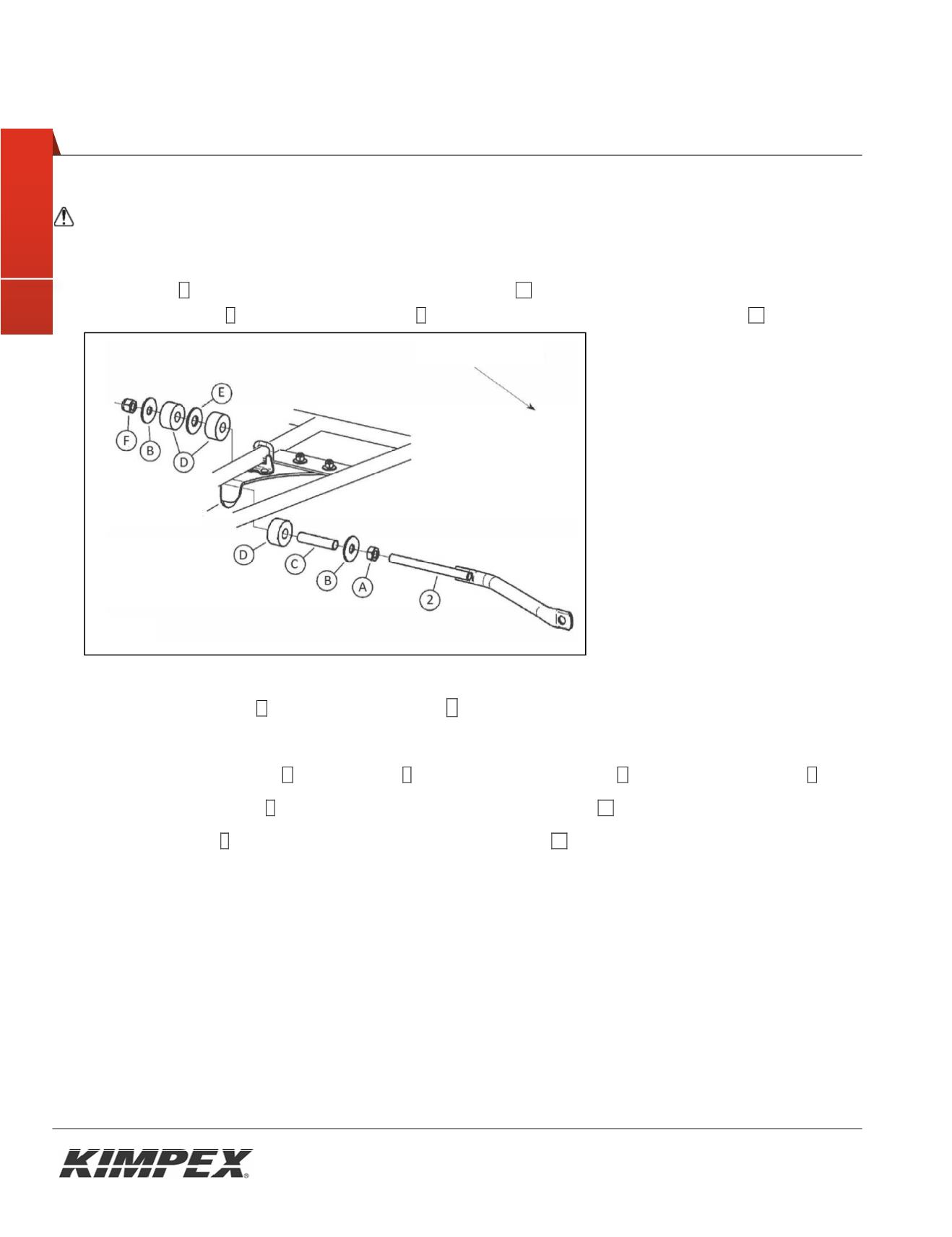
6
Rear anti-rotation arm installation
CAUTION:
Installation of the anti-rotation arm must be done before the installation of the track system on the
vehicle.
1) Screw the nut
A
onto the threaded part of the anti-rotation tube
02
.
2) Insert the flat washer
B
and the steel slider sleever
C
onto the threaded part of the anti-rotation tube
02
.
3) Insert the rubber bushing
D
over the steel slider sleeve C
4) Slide the anti-rotation assembly into the hole on the bottom of the rear suspension bracket (see
figure 4
)
5) Insert one (1) rubber bushing
D
, the flat washer
E
and the other rubber bushing
D
over the steel slider sleeve
C
6) Insert the other flat washer
B
onto the threaded part of the anti-rotation tube
02
7) Screw the nylon nut
F
onto the threaded part of the anti-rotation tube
02
8) Repeat
steps 1
to
7
for the opposite side.
Fig. 4
Rear of the ATV
Rear susp bracket
MANUE D’INSTALLATION
E SEMBLE BRAS NTI-RO ATION
0
P UR SYSTÈME DE CH NILLES COMMANDER T EX. VÉHICULES SUSPENSION INDÉPENDANTE
KIMPEX INC.
/ 5355, rue St-Roch / Drummondville (Québec) Canada / J2B 6V4
KIMPEX USA
/ 100 Walnut Street / Champlain (New York) / 12919
2810479-01-32
•
A-2810479-01-32-FR
•
Lithographié au Canada / Litho’d in Canada
5
INSTALLATION
Installation du bras anti-rotation sur le châssis avant
ATTENTION
: L’installation du bras anti-rotation doit-être faite avant l’installation du système de chenilles sur le
véhicule.
1) Retirer le capuchon de plastique
39
,
2) Assembler l'extrémité libre de l'anti-rotation avant
C
dans le trou prévu à cet effet sur le châssis de l'ensemble de
chenilles à l'aide du boulon
F
, de la rondelle
K
, de l'espaceur de serrage
E
, de la rondelle de néoprène
D
, les rondelles
fender
L
et d'un écrou autobloquant
I
.
Consultez la Figure 3.
Appliquer un couple de serrage de 23 lb-pi
AVERTISSEMENT: Attention, plusieurs trous de boulonnage sont disponibles sur la plaque de fixation de l'anti-rotation
avant; prendre celui qui fera en sorte que l'ensemble de chenilles soit correctement en appui au sol.
3) Réinstaller le capuchon de plastique
39
retiré à l'
étape 1.
4) Répéter les
étapes 1à 3
pour le côté opposé.
Fig. 3


