3/7
ATV
INSTALLATION MANUAL
FRONT AND REAR MOUNTING BRACKET KIT
KIMPEX N
o
375915
FOR COMMANDER TRACK SYSTEM AND KAWASAKI BRUTE FORCE 650 RIGID VEHICLE
KIMPEX INC.
/ 5355, rue St-Roch / Drummondville (Québec) Canada / J2B 6V4
KIMPEX USA
/ 100 Walnut Street / Champlain (New York) / 12919
2810506
•
A-2810506-EN
•
Lithographié au Canada / Litho’d in Canada
3
Front A-arm bracket Installation
WARNING
1.
The vehicle must be
immobilized
and the
engine turned off
and cooled.
2.
Always wear
safety glasses
during installation, adjustment or repair.
3.
Please read and ensure you
have understood the warnings
and guidelines.
4.
Make sure the vehicle is
safely secured in place
by a system dedicated to this use (jack stands and hoist) and that it is supported or
fixed on locations that are not likely to break, bend or slip. A hydraulic jack is not safe; nor is a log. The vehicle must be not able to move.
The installation requires that the vehicle is in two-wheel drive
mode with the gearbox in neutral. After lifting the vehicle and
removing the wheels:
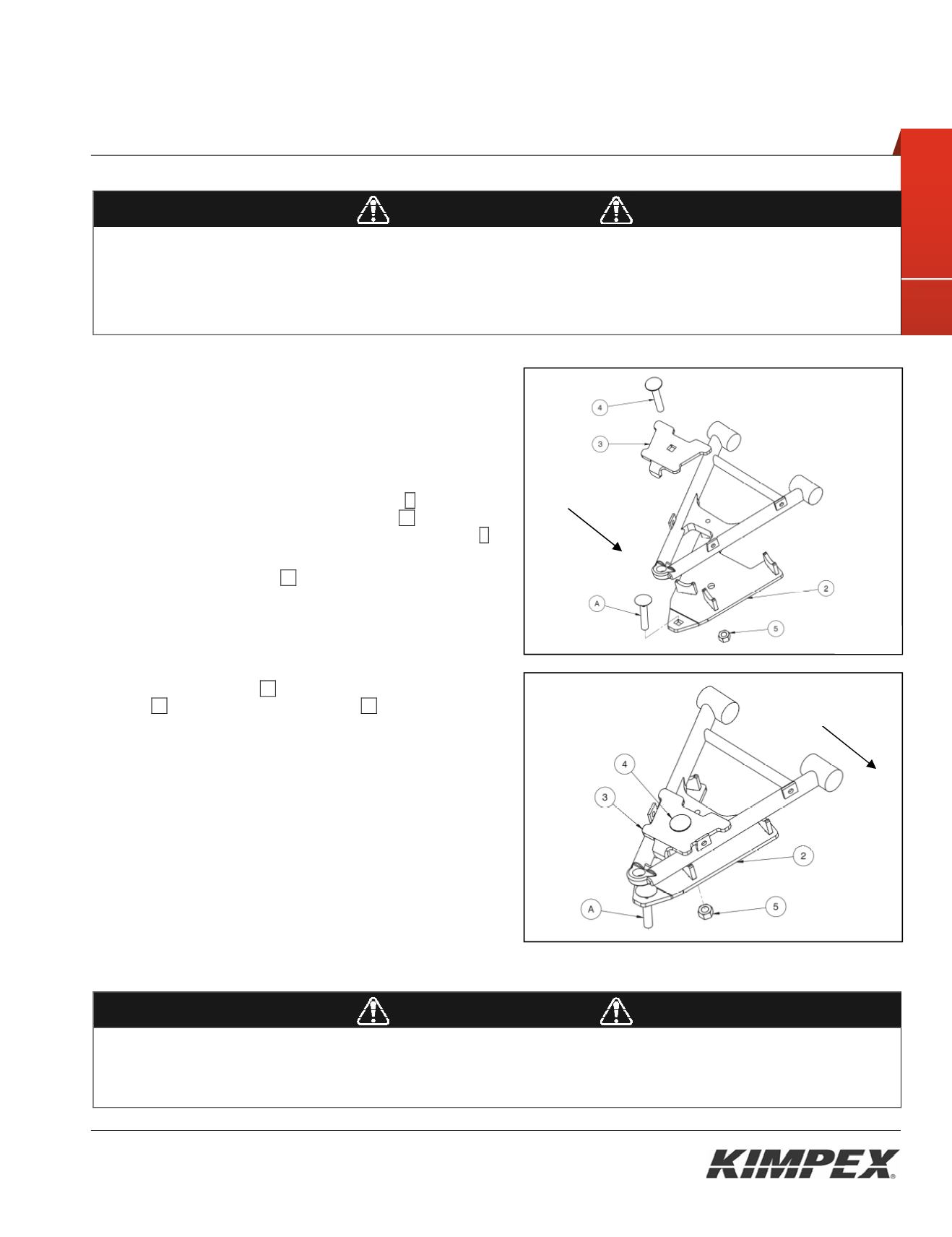
1) Remove the universal joint guard. Keep the parts for later
reinstallation.
2) Insert the M12-1.75 X 65 mm carriage bolt
A
in the hole
identified by a label on the A-arm bracket
02
. See
figure 2.
In the packaging, this bolt is mounted on the rod end
C
of
the front anti-rotation arm.
3) Lean the A-arm bracket
02
under the suspension arm
taking care that the suspension arm tubes are firmly
pressed down on the half-moon supports of the A-arm
bracket.
See Figure 2.
4) Fix the A-arm bracket to the suspension arm using the
front clamping plate
03
, the M12-1.75 X 70 mm carriage
bolt
04
and the M12-1.75 nylon nut
05
.
5) Make sure that the A-arm bracket is well positioned in the
half-moon supports and tighten all nuts in place
WARNING
1.
Do not overtorque the bolts. Some parts may be subject to deformation. If the bolts are too tight, some safety aspects could be
compromised.
2.
Be careful: an incorrectly positioned suspension bracket could give some play, which could make driving riskier as well as lead to
breakage to the vehicle, a loss of control and serious injuries.
Front of
The ATV
Fig. 2
Fig. 3
Front of
The ATV


