KIMPEX INC.
/ 5355, rue St-Roch / Drummondville (Québec) Canada / J2B 6V4
KIMPEX USA
/ 100 Walnut Street / Champlain, New York / 12919
Lithographié au Canada / Litho’d in Canada
81-828
A-497 (F-16)
PARE-CHOCS AVANT
Kimpex
#
072915
Yamaha Wolverine 1995
INSTRUCTIONS D’ASSEMBLAGE
schéma C
schéma D
schéma A
schéma B
Note :
Pour l’installation d’un treuil sur le pare-chocs avant Kimpex, veuillez utiliser les trous de position arrière,
sinon utiliser les trous avant.
1)
Insérer le pare-chocs sous le tube inférieur du grillage.
(Voir schéma A)
2)
Au tube inférieur du grillage, fixer à l’aide des brides en «U»
1-1/8” diam. X 4-5/8”
, des boulons hex.
5/16” nc X 2”
et des écrous autobloquants
5/16” nc
.
3)
Fixer le dessous du pare-chocs à l’aide des deux supports , des brides en «U»
1” diam. X 4-1/4”
, des boulons
hex.
5/16” nc X 2”
et des écrous autobloquants
5/16” nc
, au bas du cadre original.
(Voir schéma B)
4)
Fixer les supports
en dessous du pare-chocs
à l’aide des boulons hex.
5/16” nc X 3/4”
et des écrous
autobloquants
5/16” nc
. Serrer le tout.
(Voir schéma C)
5)
Insérer les capuchons de plastique aux deux extrémités du tube.
(Voir schéma D)
Réf. Description
N° d’article
Quantité
Pare-chocs avant
81-828-1000
1
Support
81-828-2000
2
Boulon hex. 5/16” nc X 3/4” S1711-00506-022 2
Boulon hex. 5/16” X 2”
S1711-00516-022 4
Réf. Description
N° d’article
Quantité
Écrou autobloquant 5/16” nc S4186-10500-022 6
Bride en «U» 1” diam. X 4-1/4” Q2116-20002
2
Bride en «U» 1” diam. X 4-5/8” Q2118-20001
2
Capuchon de plastique
S8111-00007-500 2
A-281036
2810366
ATV
Mounting instructions
FRONT AND REAR A-ARM BRACKET KIT
i pex
3 5721
For Commander Wide Track , WTX and Trex 2.0 Track Kits
2007-2009 Yamaha grizzly 700
KIMPEX INC.
/ 53 5, rue St-Roch / r
ill (
ec) Canada / J2B 6V4
KIMPEX USA
/ 100 l
lain, Ne York / 12919
ié au Canada / Litho’d in Canada
2810366
A-2810366
FRONT AND REAR A-ARM BRACKET KIT
Kimpex
#
375721
For Commander WIDE TRACK, WTX, and TREX 2.0 Track Kits
MOUNTING INSTRUCTIONS
6
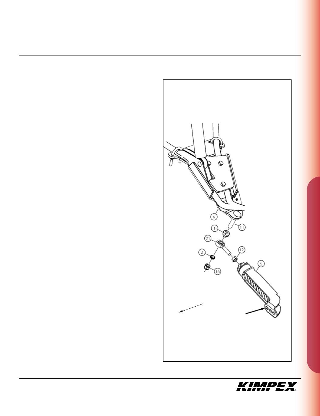
FRONT ANTI-ROTATION INSTALLATION
(see sketch F)
NOTE :
Pay special attention to the orientation given to
spacers (#1 and #2) during installation.
1)
Assemble the ba l joint (#
21
) and the
1/2” nf
nut (#
12
) to the
front anti-rotation assembly (#
5
)
.
2)
Install the large ball joint spacer (#
1
) with the narrow part facing
down onto the
1/2” nc X 2-1/2”
carriage bolt (#
11
) installed in
step
3 of the “FRONT A-ARM BRACKET INSTALLATION”
section.
3)
Install the ball joint of the front anti-rotation assembly (#
21
) onto
the bolt (#
11
), below the large ball joint spacer (#
1
). Install the
short ball joint spacer (#
2
) with the narrow part facing up,
below the anti-rotation assembly (#
21
).
4)
Tighten the assembly with the
1/2” nc
self-locking nut (#
16
).
Torque to 55 ft-lbs.
WARNING :
If the bolts are not sufficiently tightened,
there is a risk of them becoming loose, of parts detaching
and risk of loss of control over the vehicle, as well as risk
of personal injury.
5)
Rotate the anti-rotation assembly (#
5
) towards the center of the
ATV to prevent it from interfering with the installation of the
Track Kit.
NOTE :
Refer to the Track Kit manual to complete the
installation.
6)
Repeat
steps 1
to
5
for the opposite side.
IMPORTANT :
Make sure to use the correct mounting
hole on the anti-rotation (#5) when you assemble to the
Tr ck Kit (see sketch G).
ketch F
LEFT
FRONT VIEW
Front of
the ATV
MOUNTING
HOLE


