KIMPEX INC.
/ 5355, rue St-Roch / Drummondville (Québec) Canada / J2B 6V4
KIMPEX USA
/ 100 Walnut Street / Champlain, New York / 12919
Lithographié au Canada / Litho’d in Canada
81-828
A-497 (F-16)
PARE-CHOCS AVANT
Kimpex
#
072915
Yamaha Wolverine 1995
INSTRUCTIONS D’ASSEMBLAGE
schéma C
schéma D
schéma A
schéma B
Note :
Pour l’installation d’un treuil sur le pare-chocs avant Kimpex, veuillez utiliser les trous de position arrière,
sinon utiliser les trous avant.
1)
Insérer le pare-chocs sous le tube inférieur du grillage.
(Voir schéma A)
2)
Au tube inférieur du grillage, fixer à l’aide des brides en «U»
1-1/8” diam. X 4-5/8”
, des boulons hex.
5/16” nc X 2”
et des écrous autobloquants
5/16” nc
.
3)
Fixer le dessous du pare-chocs à l’aide des deux supports , des brides en «U»
1” diam. X 4-1/4”
, des boulons
hex.
5/16” nc X 2”
et des écrous autobloquants
5/16” nc
, au bas du cadre original.
(Voir schéma B)
4)
Fixer les supports
en dessous du pare-chocs
à l’aide des boulons hex.
5/16” nc X 3/4”
et des écrous
autobloquants
5/16” nc
. Serrer le tout.
(Voir schéma C)
5)
Insérer les capuchons de plastique aux deux extrémités du tube.
(Voir schéma D)
Réf. Description
N° d’article
Quantité
Pare-chocs avant
81-828-1000
1
Support
81-828-2000
2
Boulon hex. 5/16” nc X 3/4” S1711-00506-022 2
Boulon hex. 5/16” X 2”
S1711-00516-022 4
Réf. Description
N° d’article
Quantité
Écrou autobloquant 5/16” nc S4186-10500-022 6
Bride en «U» 1” diam. X 4-1/4” Q2116-20002
2
Bride en «U» 1” diam. X 4-5/8” Q2118-20001
2
Capuchon de plastique
S8111-00007-500 2
A-2810354
2810354
ATV
Mounting instructions
F ONT AND RE R A-ARM BRACKET KIT
i
3 5228
For "Commander Wide Track" and "Commander Trek" track kit Kymco 500
KIMPEX INC.
/ 5355, rue St-Roch / Drummondville (Québec) Canada / J2B 6V4
KIMPEX USA
/ 100 Walnut Street / Champlain, New York 12919
Li hographié au Canada / Lith ’d in Canada
2810354
A-2810354
RONT AND REAR A-ARM BRACKET KIT
Kimpex
#
375720
For “Commander Wide Track” and “Commander Trek” Track Kit
MOUNTING INSTRUCTIONS
8
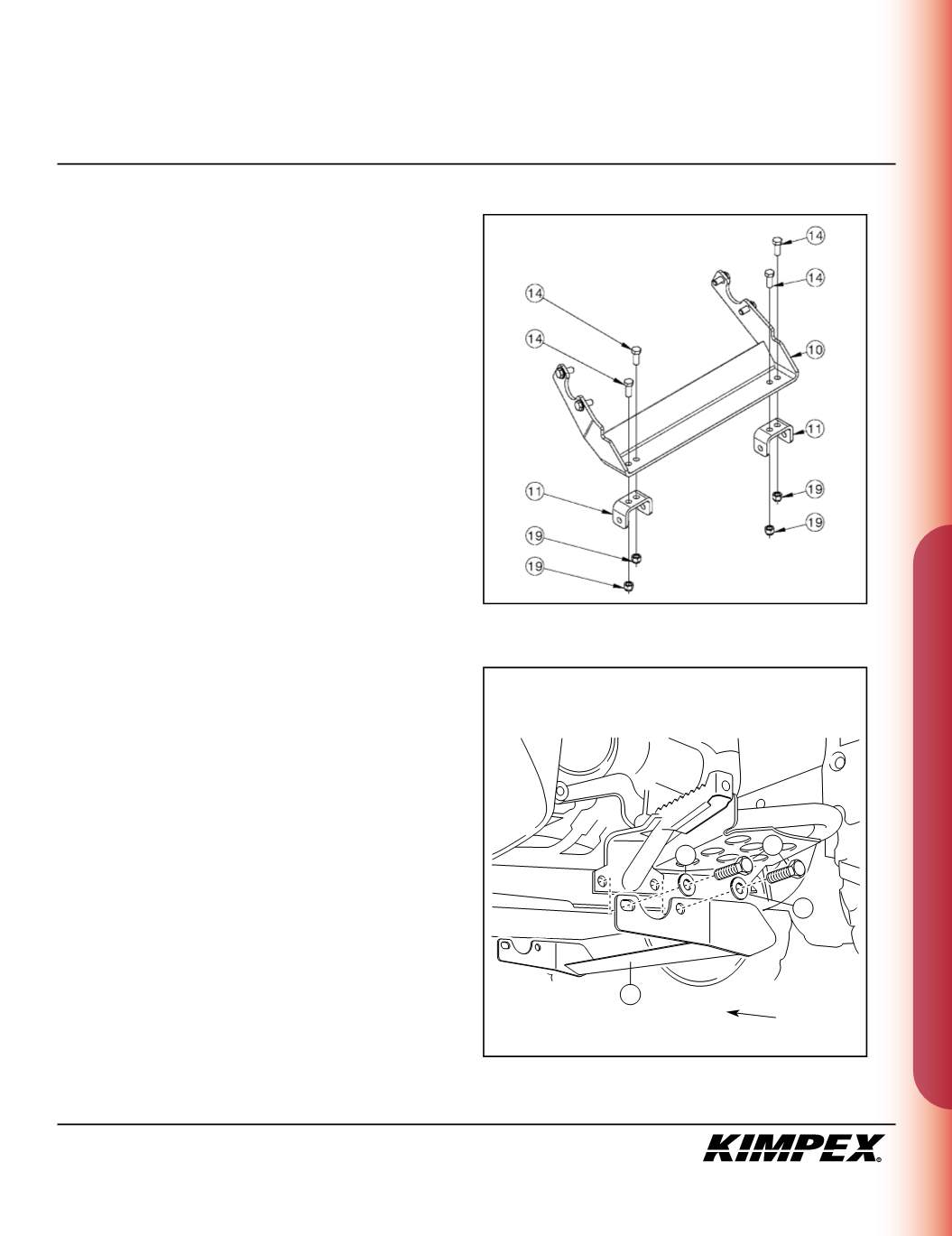
REAR BRACKET INSTALLATION
(see sketch H)
1)
Fasten the rear anti-rotation arm supports (#
11
) onto the rear
bracket (#
10
) using the
(4) 3/8” nc X 1”
hex bolts (#
14
) and the
(4)
3/8” nc
self-locking nuts (#
19
).
(see sketch I)
2)
Remove the four existing bolts retaining the footrests to frame.
3)
Fasten the rear bracket (#
10
) using the
(4) M10-1.25 X 25mm
hex
bolts (#
12
) and the
(4) 3/8” dia
flat washers (#
22
).
• TO FINISH THE INSTALLATION OF “COMMANDER
WIDE TRACK” MODELS, SEE PAGES 9 AND 10.
• TO FINISH THE INSTALLATION OF “COMMANDER
TREK” MODELS, SEE PAGES 11 AND 12.
sketch H
10
22
22
12
sketch I
LEFT
SIDE VIEW
Front of
the ATV


