KIMPEX INC.
/ 5355, rue St-Roch / Drummondville (Québec) Canada / J2B 6V4
KIMPEX USA
/ 100 Walnut Street / Champlain, New York / 12919
Lithographié au Canada / Litho’d in Canada
HOCS AVANT
Kimpex
#
072915
a Wolverine 1995
INSTRUCTIONS D’ASSEMBLAGE
schéma D
schéma B
r l’installation d’un treuil sur le pare-chocs avant Kimpex, veuillez utiliser les trous de position arrière,
n utiliser les trous avant.
pare-chocs sous le tube inférieur du grillage.
(Voir schéma A)
inférieur du grillage, fixer à l’aide des brides en «U»
1-1/8” diam. X 4-5/8”
, des boulons hex.
2”
et des écrous autobloquants
5/16” nc
.
essous du pare-chocs à l’aide des deux supports , des brides en «U»
1” diam. X 4-1/4”
, des boulons
” nc X 2”
et des écrous autobloquants
5/16” nc
, au bas du cadre original.
(Voir schéma B)
supports
en dessous du pare-chocs
à l’aide des boulons hex.
5/16” nc X 3/4”
et des écrous
uants
5/16” nc
. Serrer le tout.
(Voir schéma C)
s capuchons de plastique aux deux extrémités du tube.
(Voir schéma D)
tion
N° d’article
Quantité
cs avant
81-828-1000
1
81-828-2000
2
ex. 5/16” nc X 3/4” S1711-00506-022 2
ex. 5/16” X 2”
S1711-00516-022 4
Réf. Description
N° d’article
Quantité
Écrou autobloquant 5/16” nc S4186-10500-022 6
Bride en «U» 1” diam. X 4-1/4” Q2116-20002
2
Bride en «U» 1” diam. X 4-5/8” Q2118-20001
2
Capuchon de plastique
S8111-00007-500 2
A-2810366
2810366
ATV
Mounting instructions
FRONT AND REAR A-ARM BRACKET KIT
Kimpex
# 375721
For Commander Wide Track , WTX and Trex 2.0 Track Kits
2007-2009 Yamaha grizzly 700
KIMPEX INC.
/ 5355, rue St-Roch / Drummondville (Québec) Canada / J2B 6V4
KIMPEX USA
/ 100 Walnut Street / Champlain, New York / 12919
Lithographié au Canada / Litho’d in Canada
2810366
A-2810366
FRONT AND REAR A-ARM BRACKET KIT
Kimpex
#
375721
For Commander WIDE TRACK, WTX, and TREX 2.0 Track Kits
MOUNTING INSTRUCTIONS
9
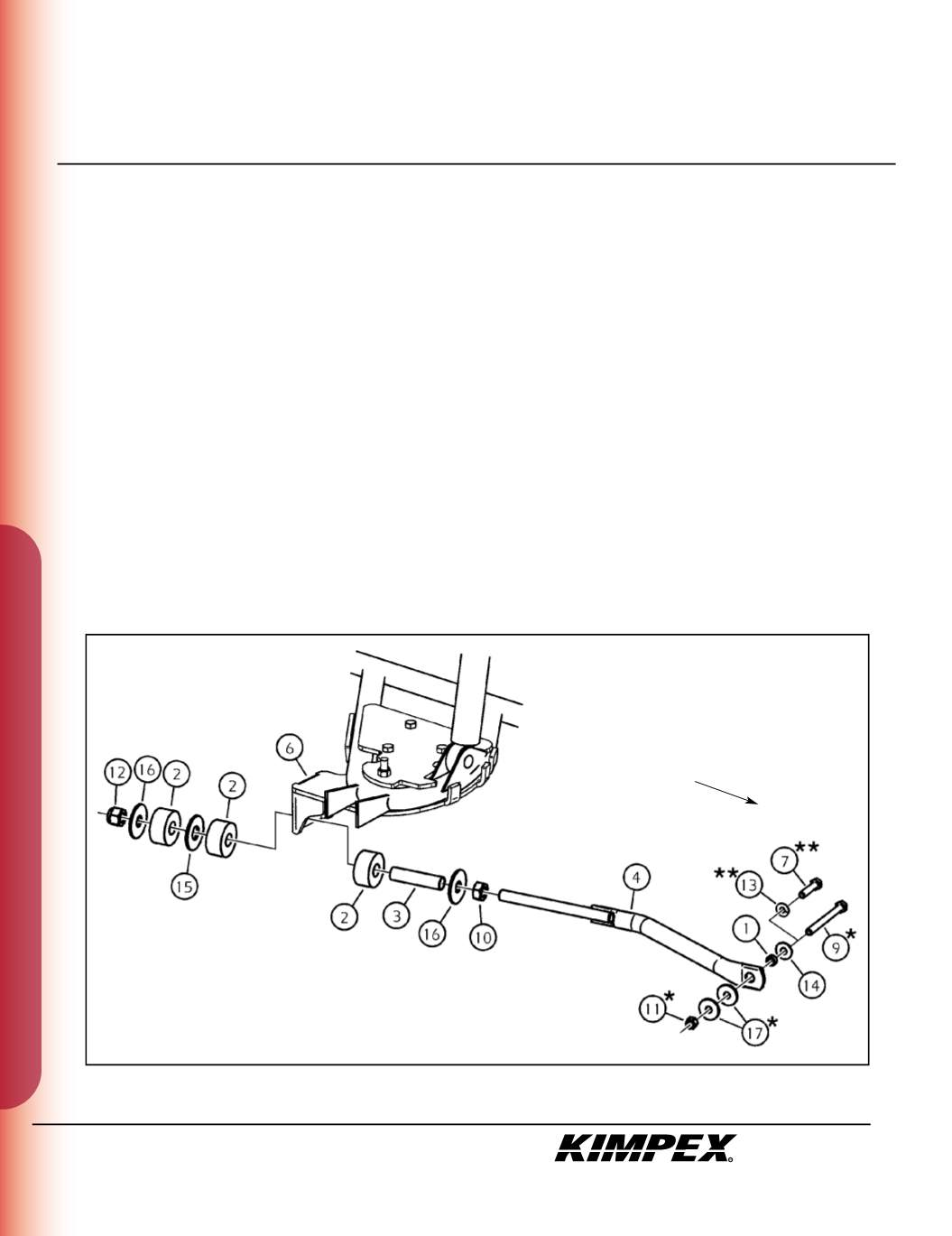
REAR ANTI-ROTATION INSTALLATION
(see sketch J)
1)
Screw the
5/8” nc
nut (#
10
) onto the threaded part of the anti-rotation tube (#
4
).
2)
Install the
17mm I.D. X 50mm O.D. X 3mm
flat washer (#
16
) and the bushing spacer tube (#
3
) onto the threaded part of the anti-rotation
tube (#
4
).
3)
Install the rubber bushing (#
2
) over the bushing spacer tube (#
3
).
4)
Slide the anti-rotation assembly into the hole on the bottom of the rear A-arm bracket (#
6
).
5)
Install the rubber bushing (#
2
), the
3/4” I.D. X 2” O.D. X 1/8”
flat washer (#
15
), and the other rubber bushing (#
2
) over the bushing spacer
tube (#
3
).
6)
Install the
17mm I.D. X 50mm O.D. X 3mm
flat washer (#
16
) onto the threaded part of the anti-rotation tube (#
4
).
7)
Screw the
5/8” nc
self-locking nut (#
12
) onto the threaded part of the anti-rotation tube (#
4
). Do not overtighten.
NOTE :
Refer to the Track Kit manual to complete the installation.
8)
Repeat
steps 1
to
7
for the opposite side.
NOTE :
Under extreme conditions of use of the Track Kit, it is possible that the tracks come into contact with the plastics
of the vehicle.
sketch J
LEFT
REAR VIEW
Rear of the ATV
*
“Commander Wide Track” Models Only.
**
“Commander TREX 2.0” Models Only.


