6/9
ATV
KIMPEX INC.
/ 5355, rue St-Roch / Drummondville (Québec) Canada / J2B 6V4
KIMPEX USA
/ 100 Walnut Street / Champlain, New York / 12919
Lithographié au Canada / Litho’d in Canada
2810370
A-2810370 Rev. A
FRONT AND REAR A-ARM BRACKET KIT
Kimpex
#
374425
For Commander TREX UTV Track Kit
MOUNTING INSTRUCTIONS
6
Front of the ATV
MOUNTING
HOLE
sketch E
LEFT
FRONT VIEW
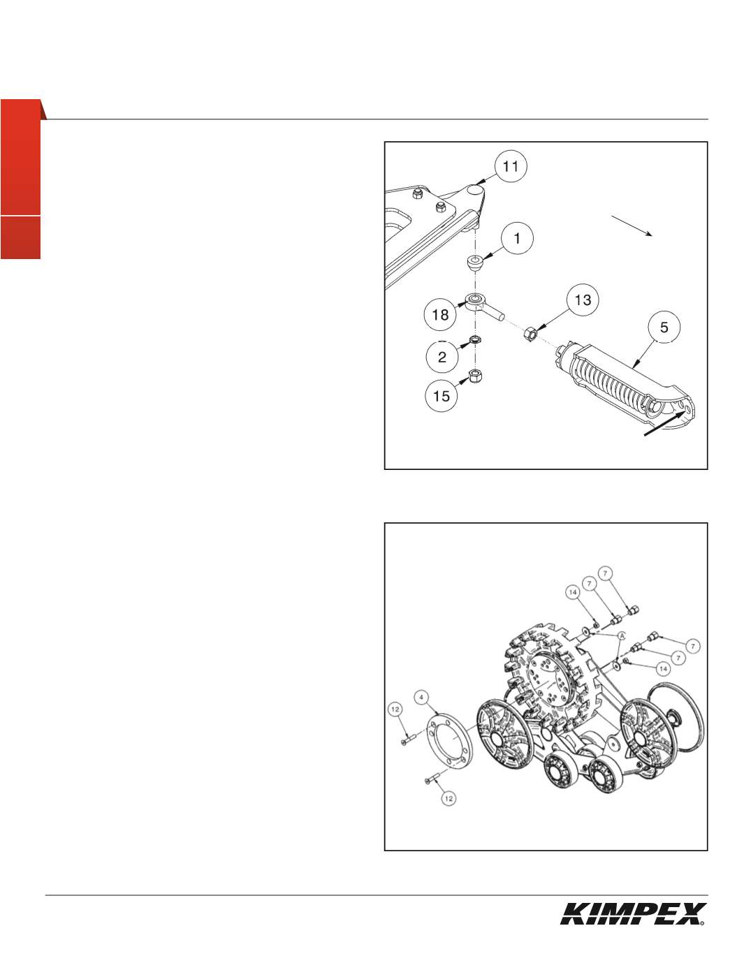
FRONT ANTI-ROTATION INSTALLATION
(see sketch E)
NOTE:
Pay special attention to the orientation given to
spacers (#1 and #2) during installation.
1)
Assemble the ball joint (#
18
) and the
1/2” nf
nut (#
13
) to the
front anti-rotation assembly (#
5
).
2)
Install the large ball joint spacer (#
1
) with the narrow part facing
down onto the
1/2” nc X 2-1/2”
carriage bolt (#
11
) installed in
step
3 at the «FRONT A-ARM BRACKET INSTALLATION» section
.
3)
Install the ball joint of the anti-rotation assembly (#
18
) onto the
bolt (#
11
), below the large ball joint spacer (#
1
).
Install the short ball joint spacer (#
2
) with the narrow part facing
up, below the anti-rotation assembly (#
5
).
4)
Tighten the assembly with the
1/2” nc
self-locking nut (#
15
).
Torque to 65 ft-lbs.
WARNING:
If the bolts are not sufficiently tightened,
there is a risk of them becoming loose, of parts detaching
and risk of loss of control over the vehicle, as well as risk
of personal injury.
5
)
Rotate the anti-rotation assembly (#
5
) towards the center of the
ATV to prevent it from interfering with the installation of the
track kit.
6)
Repeat
steps 1
to
5
for the opposite side.
MAIN AXLE ADAPTER INSTALLATION
(see sketch F)
1)
Remove and discard two bolts retaining the sprocket to the
main axle of the track kit. Retain the flat washers.
NOTE:
Pay special attention to the orientation given to
the main axle adapter (#4) during installation. The lip, of
the main axle adapter, must fit perfectly the circumfer-
ence of the main axle.
2)
Position the main axle adapter (#
4
) and fasten using the
(2) 3/8” nc X 2-1/4”
Allen socket machine screws (#
12
), the flat
washers (#
A
) removed in
step 1
, and the
(2) 3/8" nc
self-locking
nuts (#
14
). Torque to 20 ft-lbs.
3)
Install the Track Kit onto the hub of the ATV using the
(4) M10-1.25
“T” nuts (#
7
). Torque to 25 ft-lbs.
NOTE:
Recheck torque of the “T” nuts (#7) after one
hour of use.
4)
Repeat
steps 1
to
3
for the opposite side.
sketch F


