9/9
ATV
KIMPEX INC.
/ 5355, rue St-Roch / Drummondville (Québec) Canada / J2B 6V4
KIMPEX USA
/ 100 Walnut Street / Champlain, New York / 12919
Lithographié au Canada / Litho’d in Canada
2810370
A-2810370 Rev. A
FRONT AND REAR A-ARM BRACKET KIT
Kimpex
#
374425
For Commander TREX UTV Track Kit
MOUNTING INSTRUCTIONS
9
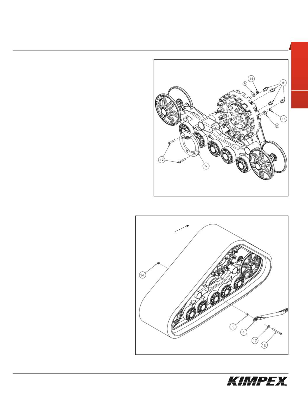
MAIN AXLE ADAPTER INSTALLATION
(see sketch J)
1)
Remove and discard two bolts retaining the sprocket to the main
axle of the track kit. Retain the flat washers.
NOTE :
Pay special attention to the orientation given to
the main axle adapter (#5) during installation. The lip, of
the main axle adapter, must fit perfectly the circumfer-
ence of the main axle.
2)
Position the main axle adapter (#
5
) and fasten using the
(2) 3/8” nc
X 2-1/4”
Allen socket machine screws (#
12
), the flat washers (#
A
)
removed in
step 1
, and the
(2) 3/8" nc
self-locking nuts (#
14
).
Torque to 20 ft-lbs.
3)
Install the track kit onto the hub of the ATV using the
(4) 3/8”-24
“T”
nuts (#
6
). Torque to 25 ft-lbs.
NOTE:
Recheck torque of the “T” nuts (#6) after one hour
of use.
4)
Repeat
steps 1
to
3
for the opposite side.
sketch J
REAR ANTI-ROTATION INSTALLATION
(see sketch K)
1)
Assemble the free extremity of the rear anti-rotation
(#
4
) to the hole made for this purpose in the plastic
frame of the Track Kit using the
3/8” nc X 4-1/2”
hex bolt
(#
10
), the
3/8” dia
flat washer (#
12
), the tightening
spacer (#
1
), and the
3/8” nc
self-locking nut (#
14
).
Apply a tightening torque of 23 ft-lbs.
2)
Repeat
step 1
for the opposite side.
NOTE:
Refer to the track kit manual to complete
the installation.
sketch K
LEFT
REAR VIEW
Front of
the ATV


