KIMPEX INC.
/ 5355, rue St-Roch / Drummondville (Québec) Canada / J2B 6V4
KIMPEX USA
/ 100 Walnut Street / Champlain, New York / 12919
Lithographié au Canada / Litho’d in Canada
81-828
A-497 (F-16)
PARE-CHOCS AVANT
Kimpex
#
072915
Yamaha Wolverine 1995
INSTRUCTIONS D’ASSEMBLAGE
schéma C
schéma D
schéma A
schéma B
Note :
Pour l’installation d’un treuil sur le pare-chocs avant Kimpex, veuillez utiliser les trous de position arrière,
sinon utiliser les trous avant.
1)
Insérer le pare-chocs sous le tube inférieur du grillage.
(Voir schéma A)
2)
Au tube inférieur du grillage, fixer à l’aide des brides en «U»
1-1/8” diam. X 4-5/8”
, des boulons hex.
5/16” nc X 2”
et des écrous autobloquants
5/16” nc
.
3)
Fixer le dessous du pare-chocs à l’aide des deux supports , des brides en «U»
1” diam. X 4-1/4”
, des boulons
hex.
5/16” nc X 2”
et des écrous autobloquants
5/16” nc
, au bas du cadre original.
(Voir schéma B)
4)
Fixer les supports
en dessous du pare-chocs
à l’aide des boulons hex.
5/16” nc X 3/4”
et des écrous
autobloquants
5/16” nc
. Serrer le tout.
(Voir schéma C)
5)
Insérer les capuchons de plastique aux deux extrémités du tube.
(Voir schéma D)
Réf. Description
N° d’article
Quantité
Pare-chocs avant
81-828-1000
1
Support
81-828-2000
2
Boulon hex. 5/16” nc X 3/4” S1711-00506-022 2
Boulon hex. 5/16” X 2”
S1711-00516-022 4
Réf. Description
N° d’article
Quantité
Écrou autobloquant 5/16” nc S4186-10500-022 6
Bride en «U» 1” diam. X 4-1/4” Q2116-20002
2
Bride en «U» 1” diam. X 4-5/8” Q2118-20001
2
Capuchon de plastique
S8111-00007-500 2
A-281036
2810366
ATV
Mounting instructions
FRONT AND REAR A-ARM BRACKET KIT
i pex
3 5721
For Commander Wide Track , WTX and Trex 2.0 Track Kits
2007-2009 Yamaha grizzly 700
KIMPEX INC.
/ 5355, rue St-Roch / Drummondville (Québec) Canada / J2B 6V4
KIMPEX USA
/ 100 Walnut Street / Champlain, New York / 12919
Lithographié au Canada / Litho’d in Canada
2810366
A-2810366
FRONT AND REAR A-ARM BRACKET KIT
Kimpex
#
375721
For Commander WIDE TRACK, WTX, and TREX 2.0 Track Kits
MOUNTING INSTRUCTIONS
8
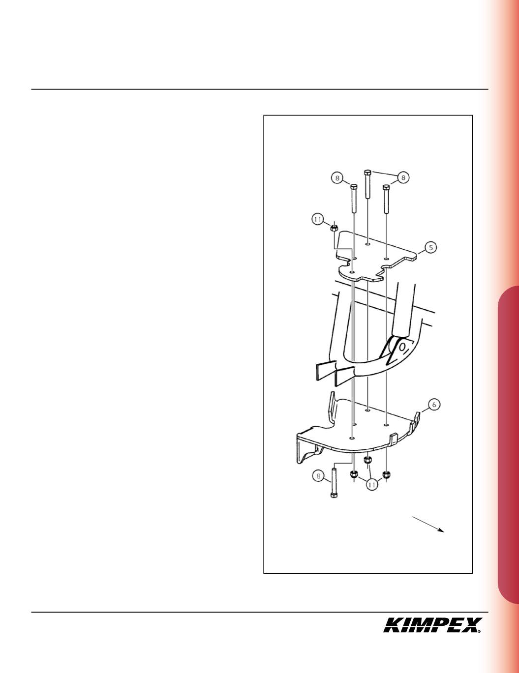
REAR A-ARM BRACKET INSTALLATION
(see sketch I)
WARNING :
Prior to installation, turn off the engine, put
in two-wheel driving mode, and block the wheels.
1)
Raise the rear of the ATV off the ground and remove the wheels.
WARNING :
When the ATV is raised, make sure that it is
properly secured/supported to prevent it from
accidentally falling during the installation of the A-arm
brackets. If not properly secured/supported, serious
physical injury could occur.
2)
Remove the rear left CV shield. Do not discard. They will be
reinstalled later.
3)
Position the rear left A-arm bra ket (#
6
) under the lower rear
A-arm so that the two parts fit snugly.
4)
Install the rear A-arm clamping plate (#
5
) over the lower rear A-
arm and fasten it to the A-arm bracket (#
6
) using
(4)
3/8” nc X 2-1/2”
hex bolts (#
8
) and
(4) 3/8” nc
self-locking n ts (#
11
).
Torque to 20 ft-lbs.
IMPORTANT :
Tighten in a manner not to permanently
deform the assembly.
sketch I
LEFT
REAR VIEW
Rear of the ATV


