5/7
ATV
INSTALLATION MANUAL
FRONT AND REAR MOUNTING BRACKET KIT
KIMPEX N
°
375911
FOR COMMANDER TRACK SYSTEM AND POLARIS SPORTSMAN 95-04 VEHICLES
KIMPEX INC.
/ 5355, rue St-Roch / Drummondville (Québec) Canada / J2B 6V4
KIMPEX USA
/ 100 Walnut Street / Champlain (New York) / 12919
2810496
•
A-2810496-EN
•
Lithographié au Canada / Litho’d in Canada
5
Front A-arm brackets installation
WARNING
1.
The vehicle must be
immobilized
and the
engine turned off
and cooled.
2.
Always wear
safety glasses
during installation, adjustment or repair.
3.
Please read and ensure you
have understood the warnings
and guidelines.
4.
Make sure the vehicle is
safely secured in place
by a system dedicated to this use (jack stands and hoist) and that it is supported or
fixed on locations that are not likely to break, bend or slip. A hydraulic jack is not safe; nor is a log. The vehicle must be not able to move.
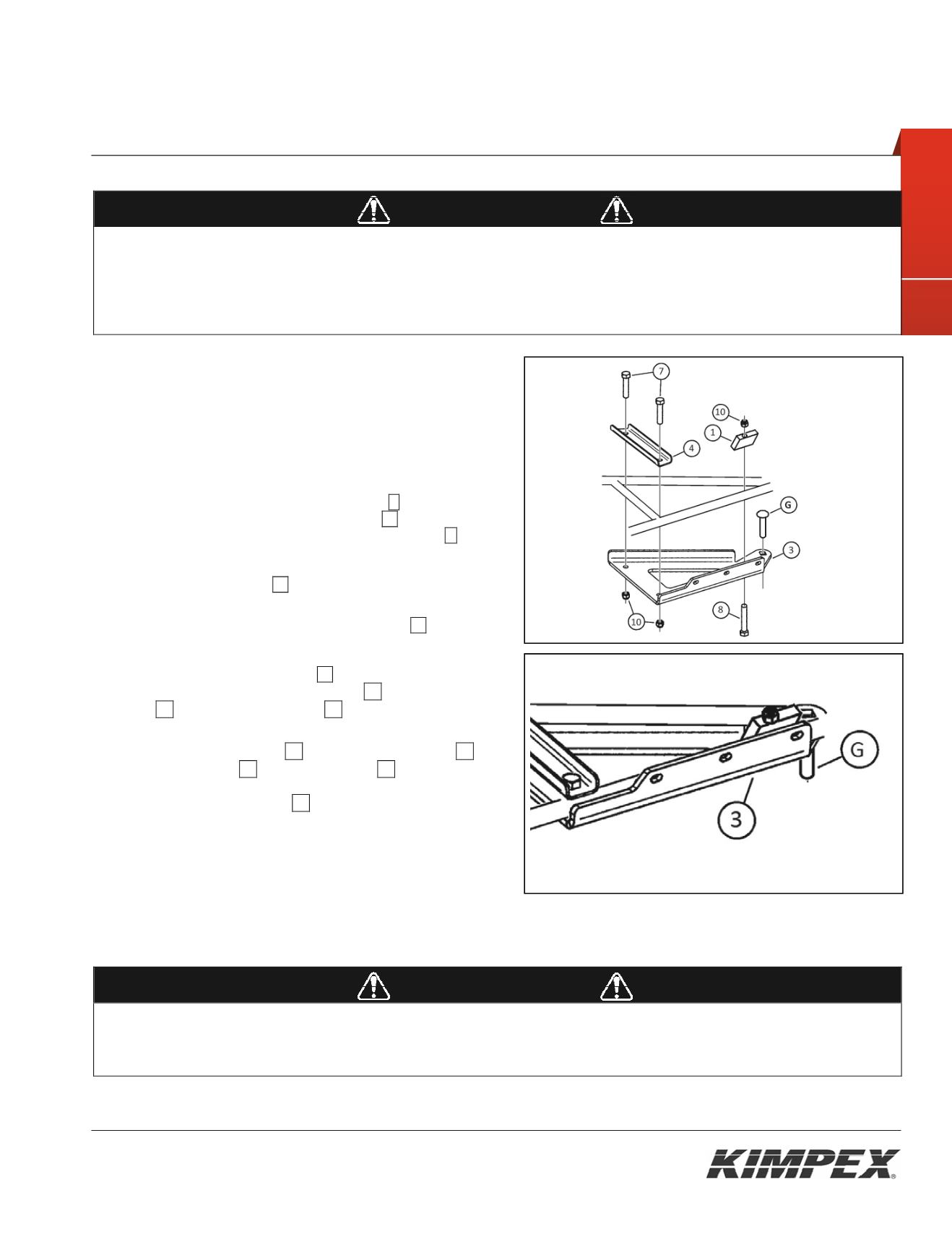
The installation requires that the vehicle is in two-wheel drive
mode with the gearbox in neutral. After lifting the vehicle and
removing the wheels:
1) Remove the universal joint guard. Keep the parts for later
reinstallation.
2) Insert the M12-1.75 x 65-mm carriage bolt
G
in the hole
identified by a label on the a-arm bracket
03
. See
Figure 4.
In
the packaging, this bolt is mounted on the rod end
M
of the
front anti-rotation arm.
3) Lean the A-arm bracket
03
under the lower front A-arm so
that the two parts fits snugly.
Note : The angled part of the front clamping plate
04
should face
the rear of the ATV
4) Install the front clamping plate
04
above the lower front A-
arm and fasten it to the A-arm bracket 03 using two (2) hex.
bolts 07 and two (2) nylon nuts 10 (Screw the first threads
only).
5) Install the clamping block 01 onto the A-arm bracket 03
using the hex bolt 08 and the nylon nut 10. Appliquer un
couple de serrage de 20 lb-pi.
Attention à l'orientation à
donner au bloc de serrage 01 lors de son installation.
6) Serrer les boulons installés à l'
étape 4
de sorte qu'ils soient
appuyés fermement. Appliquer un couple de serrage de 20
lb-pi.
7) Replacer le protecteur de cardan à l'aide des boulons
originaux enlevés à l'
étape 1.
8)
Répéter les
étapes 1
à
7
pour le côté opposé
WARNING
1.
Do not overtorque the bolts. Some parts may be subject to deformation. If the bolts are too tight, some safety aspects could be
compromised.
2.
Be careful: an incorrectly positioned A-arm bracket could give some play, which could make driving riskier as well as lead to breakage to
the vehicle, a loss of control and serious injuries.
Fig. 4
Fig. 5


