5/10
ATV
KIMPEX INC.
/ 5355, rue St-Roch / Drummondville (Québec) Canada / J2B 6V4
KIMPEX USA
/ 100 Walnut Street / Champlain, New York / 12919
Lithographié au Canada / Litho’d in Canada
2810374
A-2810374 Rev. A
FRONT AND REAR A-ARM BRACKET KIT
Kimpex
#
374445
For Commander WIDE TRACK, WTX, and TREX UTV Track Kits
MOUNTING INSTRUCTIONS
5
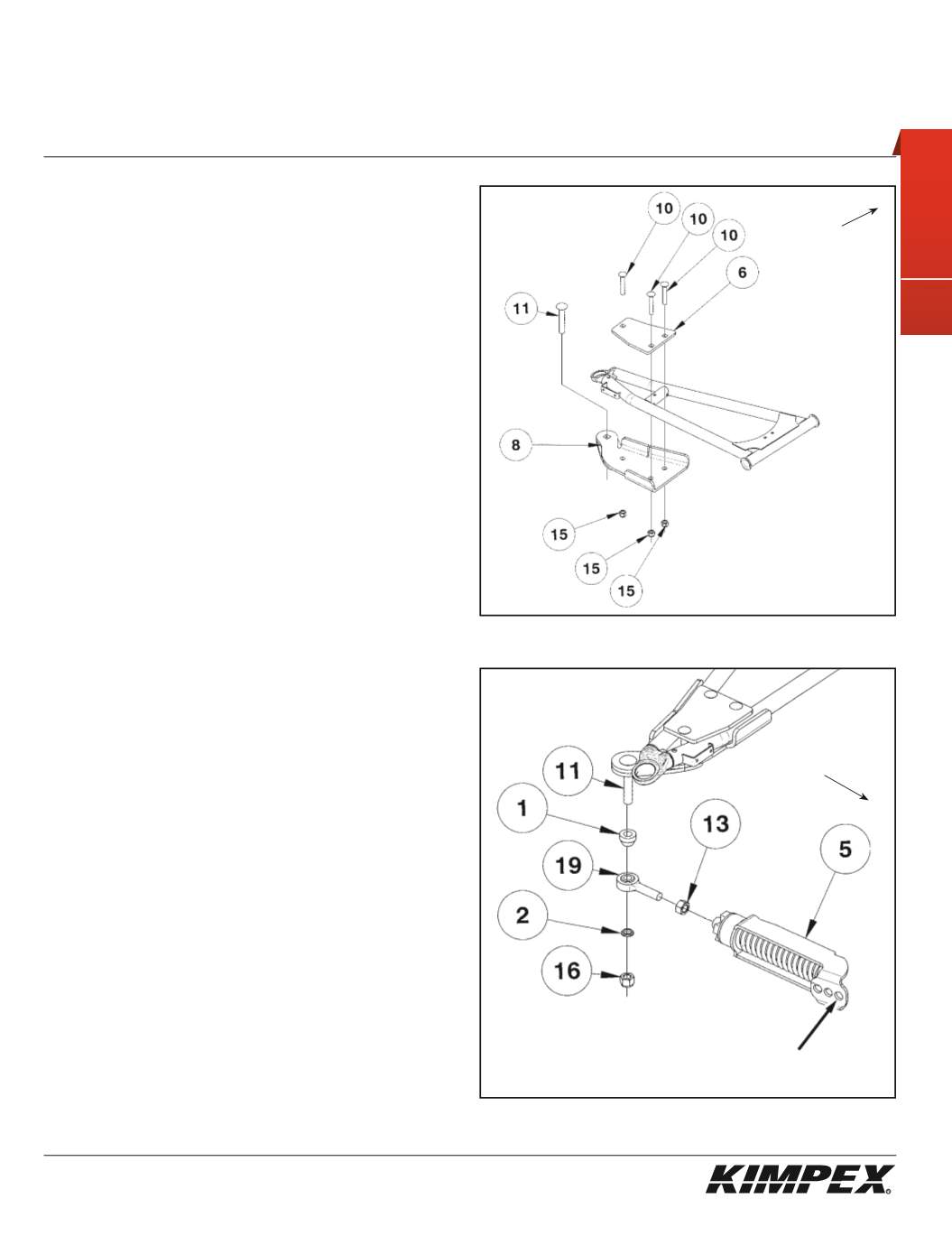
FRONT A-ARM BRACKET INSTALLATION
(see sketch D)
WARNING:
Prior to installation, turn off the engine, put in
two-wheel driving mode, and block the wheels.
1)
Raise the front of the ATV off the ground and remove the wheels.
WARNING:
When the ATV is raised, make sure that it is
properly secured/supported to prevent it from accidentally
falling during the installation of the sub-tables. If not
properly secured/supported, serious physical injury could
occur.
2)
Remove the front left CV shield. Do not discard. They will be
reinstalled later.
3)
Insert the
1/2” nc X 3”
carriage bolt (#
11
) into the hole intended in the
front left A-arm bracket (#
8
).
4)
Install the front left A-arm bracket (#
8
) under the lower front
a-arm so that the two parts fit snugly.
5)
Install the front A-arm clamping plate (#
6
) above the lower front
a-arm and fasten it to the A-arm bracket (#
8
) using the
(4) 3/8” nc X
2-1/4”
carriage bolts (#
10
) and the
(4) 3/8” nc
self-locking nuts (#
15
).
Tighten the bolts and make sure they fit snugly. Torque to 20 ft-lbs.
IMPORTANT:
Tighten in a manner not to permanently
deform the assembly.
6)
Repeat
steps 2
to
5
for the opposite side.
FRONT ANTI-ROTATION INSTALLATION
(see sketch E)
NOTE:
Pay special attention to the orientation given to
spacers (#1 and #2) during installation.
1)
Assemble the ball joint (#
19
) and the
1/2” nf
nut (#
13
) to the front
anti-rotation assembly (#
5
).
2)
Install the large ball joint spacer (#
1
) with the narrow part facing
down onto the
1/2” nc X 3”
carriage bolt (#
11
) installed in
step 3 at
the «FRONT A-ARM BRACKET INSTALLATION» section
.
3)
Install the ball joint of the anti-rotation assembly (#
19
) onto the bolt
(#
11
), below the large ball joint spacer (#
1
).
Install the short ball joint spacer (#
2
) with the narrow part facing up,
below the anti-rotation assembly (#
5
).
4)
Tighten the assembly with the
1/2” nc
self-locking nut (#
16
).
Torque to 65 ft-lbs.
WARNING:
If the bolts are not sufficiently tightened, there
is a risk of them becoming loose, of parts detaching and risk
of loss of control over the vehicle, as well as risk of personal
injury.
5
)
Rotate the anti-rotation assembly (#
5
) towards the center of the ATV
to prevent it from interfering with the installation of the track kit.
6)
Repeat
steps 1
to
5
for the opposite side.
sketch E
LEFT
FRONT VIEW
LEFT
FRONT VIEW
Front of
the ATV
sketch D
Front of
the ATV
MOUNTING HOLE


