7/10
ATV
KIMPEX INC.
/ 5355, rue St-Roch / Drummondville (Québec) Canada / J2B 6V4
KIMPEX USA
/ 100 Walnut Street / Champlain, New York / 12919
Lithographié au Canada / Litho’d in Canada
2810374
A-2810374 Rev. A
FRONT AND REAR A-ARM BRACKET KIT
Kimpex
#
374445
For Commander WIDE TRACK, WTX, and TREX UTV Track Kits
MOUNTING INSTRUCTIONS
7
COMMANDER TREX UTV
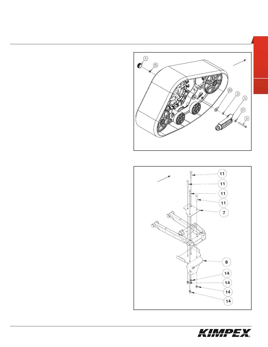
FRONT ANTI-ROTATION INSTALLATION
(see sketch H)
1)
Remove the wheel cap (#
A
).
2)
Assemble the free extremity of the front anti-rotation (#
5
) to the
hole made for this purpose in the frame of the Track Kit using the
3/8” nc X 4”
hex bolt (#
9
), the
3/8” dia
flat washer (#
17
), the
tightening spacer (#
3
), the neoprene flat washer (#
20
), and the
3/8” nc
self-locking nut (#
15
).
Apply a tightening torque of 23 ft-lbs.
WARNING:
Attention, many holes are available on the
anti-rotation fixation plate. Take the one which will make
so that the track kit is correctly in contact with the
ground.
3)
Reinstall the wheel cap (#
A
) removed in
step 1
.
4)
Repeat
steps 1
to
3
for the opposite side.
NOTE:
Refer to the track kit manual to complete the
installation.
REAR A-ARM BRACKET INSTALLATION
(see sketch I)
WARNING:
Prior to installation, turn off the engine, put
in two-wheel driving mode and the transmission in
neutral, and block the wheels.
1)
Raise the rear of the vehicle off the ground and remove the
wheels.
WARNING:
When the vehicle is raised, make sure that it
is properly secured/supported to prevent it from
accidentally falling during the installation of the A-arm
brackets. If not properly secured/supported, serious
physical injury could occur.
2)
Remove the rear left CV shield. Do not discard. They will be
reinstalled later.
3)
Place the rear left A-arm bracket (#
8
) below the rear lower A-arm
so that the two parts fit snugly.
4)
Install the rear A-arm clamping plate (#
7
) above the lower front
A-arm and fasten it to the A-arm bracket (#
8
) using the
(4)
3/8” nc X 2-1/2”
carriage bolts (#
11
), and the
(4) 3/8” nc
self-locking
nuts (#
14
). Torque to 20 ft-lbs.
IMPORTANT:
Tighten in a manner not to permanently
deform the assembly.
5)
Repeat
steps 2
to
4
for the opposite side.
sketch H
LEFT
FRONT VIEW
Front of
the ATV
sketch I
LEFT
REAR VIEW
Rear of
the ATV


