KIMPEX INC.
/ 5355, rue St-Roch / Drummondville (Québec) Canada / J2B 6V4
KIMPEX USA
/ 100 Walnut Street / Champlain, New York / 12919
Lithographié au Canada / Litho’d in Canada
A-2810161 (F-00)
28102161
3/6
ATV
MOUNTING INSTRUCTIONS
FRONT AND REAR A-ARM BRACKET KIT
Kimpex
# 373711
For "Commander" track kit / Yamaha Kodiak 400, 450 (indepndent suspension)
FRONT A-ARM BRACKET INSTALLATION
(see sketch A)
WARNING :
Prior to installation, turn off the engine, put
in two-wheel driving mode, and block the wheels.
1)
Raise the front of the ATV off the ground and remove the
wheels.
WARNING :
When the ATV is raised, make sure that it is
properly secured/supported to prevent it from
accidentally falling during the installation of the sub-
tables. If not properly secured/supported, serious
physical injury could occur.
2)
Remove the front left CV shield. Do not discard. They will be
reinstalled later.
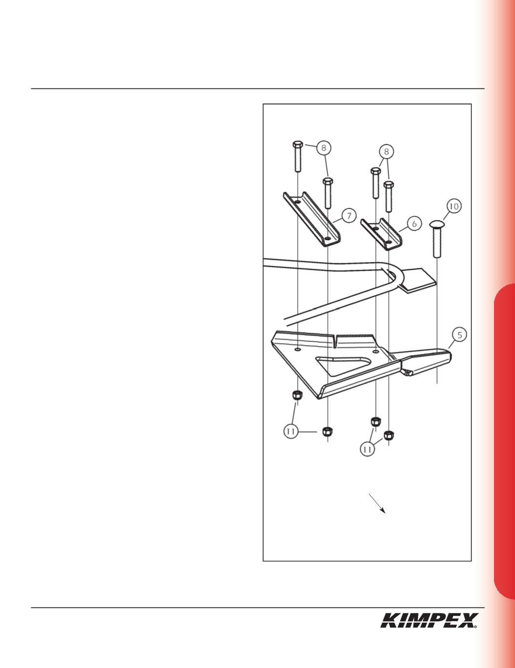
3)
Insert the
1/2” nc X 2-1/2”
carriage bolt (#
10
) into the hole
intended in the front left A-arm bracket (#
5
).
4)
Install the front left A-arm bracket (#
5
) under the lower front
A-arm so that the two parts fit snugly.
NOTE :
The angled parts of the external (#6) and
internal (#7) clamping plate should mate the A-arm
bracket (#5) as well as possible.
5)
Install the external (#
6
) and internal (#
7
) front A-arm bracket
clamping plate above the lower front A-arm and fasten it to the
A-arm bracket (#
5
) using the
(4) 3/8” nc X 2”
hex bolts (#
8
) and the
(4) 3/8” nc
self-locking nuts (#
11
). Torque to 20 ft-lbs.
IMPORTANT :
Tighten in a manner not to permanently
deform the assembly.
6)
Repeat
steps 2
to
5
for the opposite side.
sketch A
LEFT
FRONT VIEW
Front of the ATV


