KIMPEX INC.
/ 5355, rue St-Roch / Drummondville (Québec) Canada / J2B 6V4
KIMPEX USA
/ 100 Walnut Street / Champlain, New York / 12919
Lithographié au Canada / Litho’d in Canada
A-2810151 (F-00)
28102151
5/6
ATV
MOUNTING INSTRUCTIONS
FRONT AND REAR A-ARM BRACKET KIT
Kimpex
# 373610
For "Commander" track kit / Suzuki King Quad
REAR SUB-TABLE INSTALLATION
(see sketch C)
WARNING :
Prior to installation, turn off the engine, put
in two-wheel driving mode, and block the wheels.
1)
Raise the rear of the ATV off the ground and remove the wheels.
WARNING :
When the ATV is raised, make sure that it is
properly secured/supported to prevent it from
accidentally falling during the installation of the sub-
tables. If not properly secured/supported, serious
physical injury could occur.
2)
Remove the rear left CV shield. Do not discard. They will be
reinstalled later.
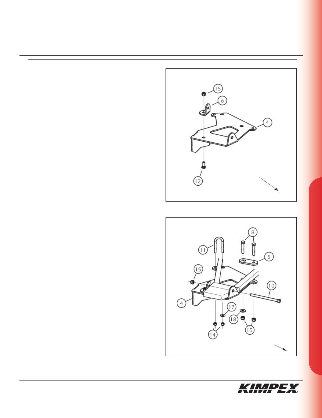
3)
Assemble the internal tightening bended plate (#
6
) onto the
rear left sub-table plate (#
4
) using the
3/8” nc X 1”
carriage bolt
(#
12
) and the
3/8” nc
self-locking nut (#
15
) (screw the first
threads only).
(see sketch D)
4)
Place the rear sub-table plate (#
4
) below the rear lower a-arm.
Install the
3/8” nc X 5-1/2”
hex bolt (#
10
) and the
3/8” nc
self-locking
nut (#
15
) above the rear lower a-arm (screw the first threads
only).
5)
Install the
5/16” nc X 2.188”
U-bolt (#
11
) over the rear lower a-arm
into the intended mounting holes of the rear sub-table plate
(#
4
). Install the
5/16” dia
flat washer (#
17
) and the
5/16” nc
self-
locking nut (#
14
) (screw the first threads only).
6)
Install the external tightening plate (#
5
) and fasten using the
(2)
3/8” nc X 2”
hex bolts (#
8
), the
3/8” dia
flat washer (#
18
), and the
(2) 3/8” nc
self-locking nuts (#
15
).
7)
Tighten all the bolts. Torque the
5/16” nc
nuts (#
14
) to 15 ft-lbs
and the
3/8” nc
nuts (#
15
) to 25 ft-lbs.
sketch C
LEFT
REAR VIEW
LEFT
REAR
VIEW
Rear of the ATV
sketch D
Rear of
the ATV


