10/15
ATV
FRONT AND REAR A-ARM BRACKET KIT
FOR ST-90 TRACK KIT
FRONT A-ARM BRACKET AND LIMITER
INSTALLATION
Prior to installation, turn off the engine, put in two-wheel
driving mode and the transmission in neutral, and block
the wheels.
WARNING
When the vehicle is raised, make sure that it is properly
secured/supported to prevent it from accidentally falling
during the installation of the A-arm brackets. If not
properly secured/supported, serious physical injury
could occur.
WARNING
1.
Raise the front of the vehicle off the ground and remove
the wheels.
2.
Remove the front CV shields.
3.
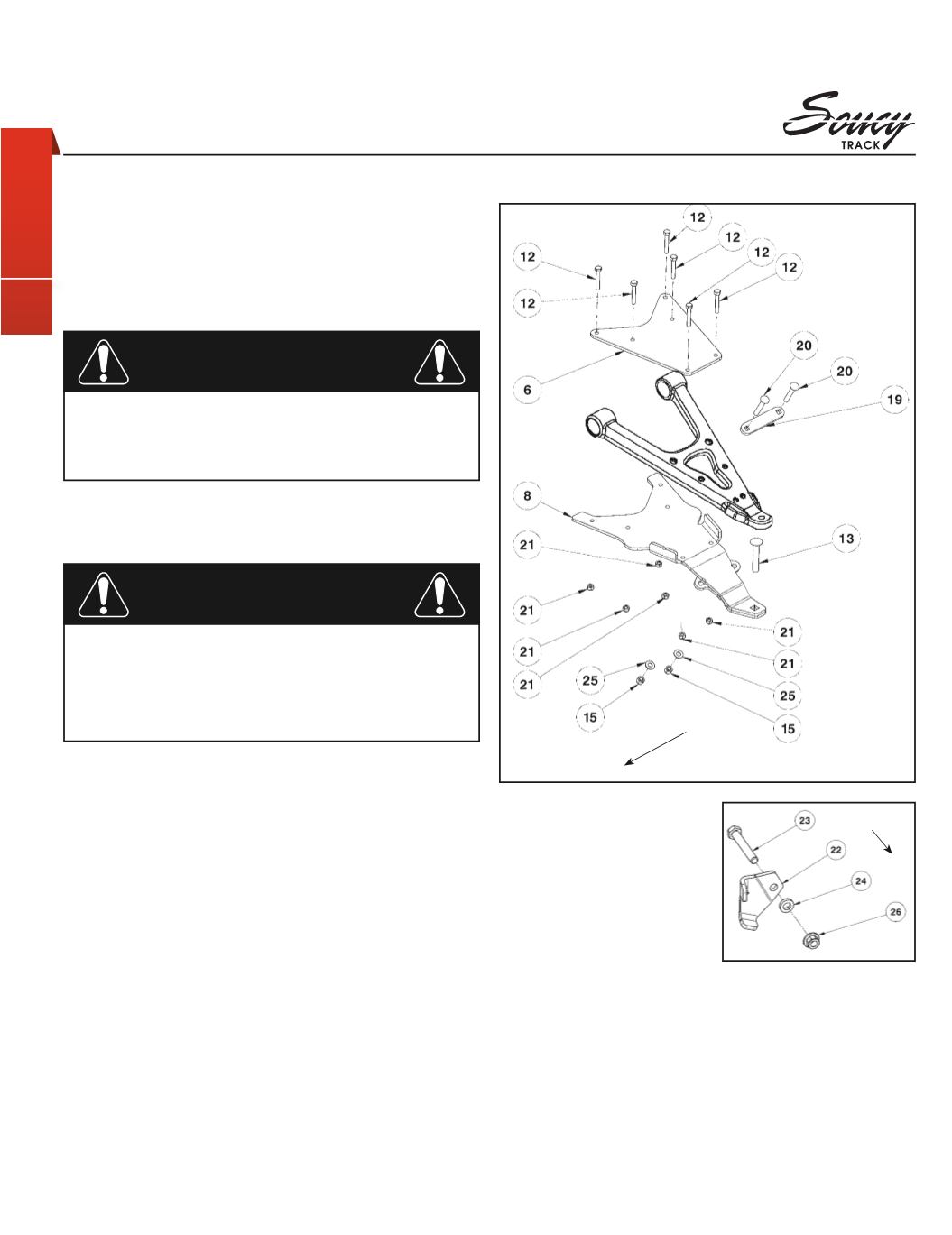
Insert the 1/2” nc X 3” carriage bolt (
#13
) into the hole
intended in the front left A-arm bracket (
#8
).
4.
Install the front left A-arm bracket (
#8
) under the lower
front A-arm so that the two parts fit snugly.
5.
Position the tightening front plate (
#6
) above the lower
front A-arm and fasten it to the front A-arm bracket (
#8
)
using the (6) 5/16” nc X 2” hex bolts (
#12
) and the (6)
5/16” nc nylock nuts (
#21
). Tighten the bolts and make
sure they fit snugly. Torque to 20 ft-lbs.
IMPORTANT: Tighten in a manner not to permanently
deform the assembly.
6.
Position and fasten the tightening plate (
#19
) using the
(2) 3/8” nc X 2-1/4” carriage bolts (
#20
), the (2) 3/8”
dia flat washers (
#25
), and the (2) 3/8” nc nylock nuts
(
#15
). Tighten the bolts and make sure they fit snugly.
Torque to 11 ft-lbs.
IMPORTANT: Tighten in a manner not to permanently
deform the assembly.
NOTE:
The right side of the vehicle must be considered when
you’re sitting on it.
7.
Insert the limiter plate
(
#22
) and the flat washer
(
#24
) on the M12 bolt
(
#23
).
WARNING: The plate
must be inserted on the
right side.
8.
Remove the existing M12
bolt and nut retaining the
A-arm to the A-arm bracket. Replace by the bolt assembly
in
step 7
.
WARNING: The bolt must be inserted from rear to front
of the vehicle.
9.
Secure with the M12 nut (
#26
) until the limiter plate (
#22
)
is deformed and fit snugly on the suspension table side.
Torque to 70 ft-lbs.
10.
Repeat
steps 2
to
9
for the opposite side.
figure 3
LEFT FRONT VIEW
FRONT
FRONT
|
KIMPEX N°
374502


