11/13
ATV
KIMPEX INC.
/ 5355, rue St-Roch / Drummondville (Québec) Canada / J2B 6V4
KIMPEX USA
/ 100 Walnut Street / Champlain, New York / 12919
Lithographié au Canada / Litho’d in Canada
2810404
A-2810404
FRONT AND REAR A-ARM BRACKET KIT
Kimpex
#
375201
For “Commander Wide Track” and “Commander Trek” Track Kit
MOUNTING INSTRUCTIONS
11
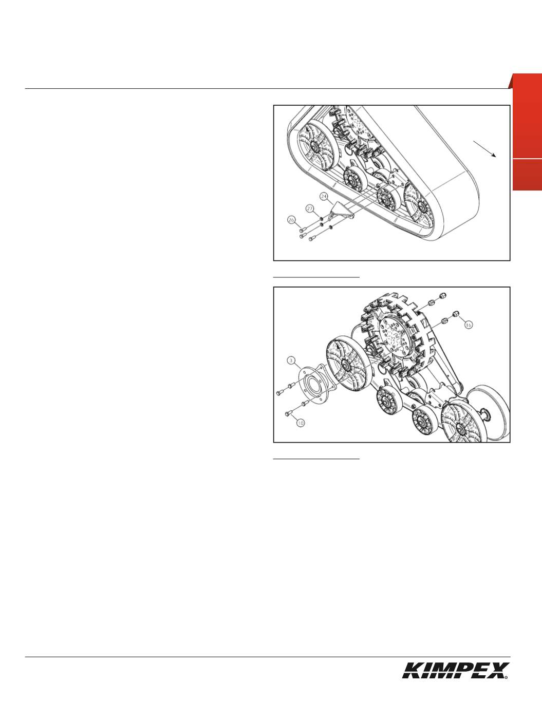
“COMMANDER TREK”
REAR ANTI-ROTATION ARM BRACKET
INSTALLATION (see sketch O)
1)
Assemble the rear right anti-rotation arm bracket (#
24
) to the
hole made for this purpose in the frame of the Track Kit using
(3)
3/8” nc X 1”
hex bolts (#
26
) and the
(3) 3/8” dia
lock washers (#
27
).
2)
Repeat for the opposite side.
“COMMANDER TREK”
MAIN AXLE ADAPTER INSTALLATION
(see sketch P)
WARNING :
Prior to installation, turn off the engine, put
in two-wheel driving mode and the transmission in
neutral, and block the wheels.
1)
Raise the rear of the ATV off the ground and remove the wheels.
WARNING :
When the ATV is raised, make sure that it is
properly secured/supported to prevent it fromaccidentally
falling during the installation. If not properly secured/
supported, serious physical injury could occur.
2)
Remove the rear right CV shield. Do not discard. They will be
reinstalled later.
3)
Install the
(4) M10 X 30mm
hex bolts (#
10
) into the threaded holes
of the main axle adapter (#
3
) as illustrated.
4)
Position and fasten the main axle adapter (#
3
) onto the hub of
the vehicle using the original wheel nuts. Apply the tightening
torque specified in your ATV owner’s manual.
5)
Position and fasten the Track Kit to the main axle adapter (#
3
)
using the
(4) M10
wheel nuts (#
16
).
Torque to 25 ft-lbs.
NOTE :
Recheck torque of the wheel nuts (#16) after
one hour of use.
6)
Repeat
steps 2
to
5
for the opposite side.
sketch O
sketch P
RIGHT REAR VIEW
Rear of
the ATV


