7/9
ATV
KIMPEX INC.
/ 5355, rue St-Roch / Drummondville (Québec) Canada / J2B 6V4
KIMPEX USA
/ 100 Walnut Street / Champlain, New York / 12919
Lithographié au Canada / Litho’d in Canada
2810398
A-2810398 Rev. A
FRONT AND REAR A-ARM BRACKET KIT
Kimpex
#
374465
For Commander TREX UTV Track Kit
MOUNTING INSTRUCTIONS
7
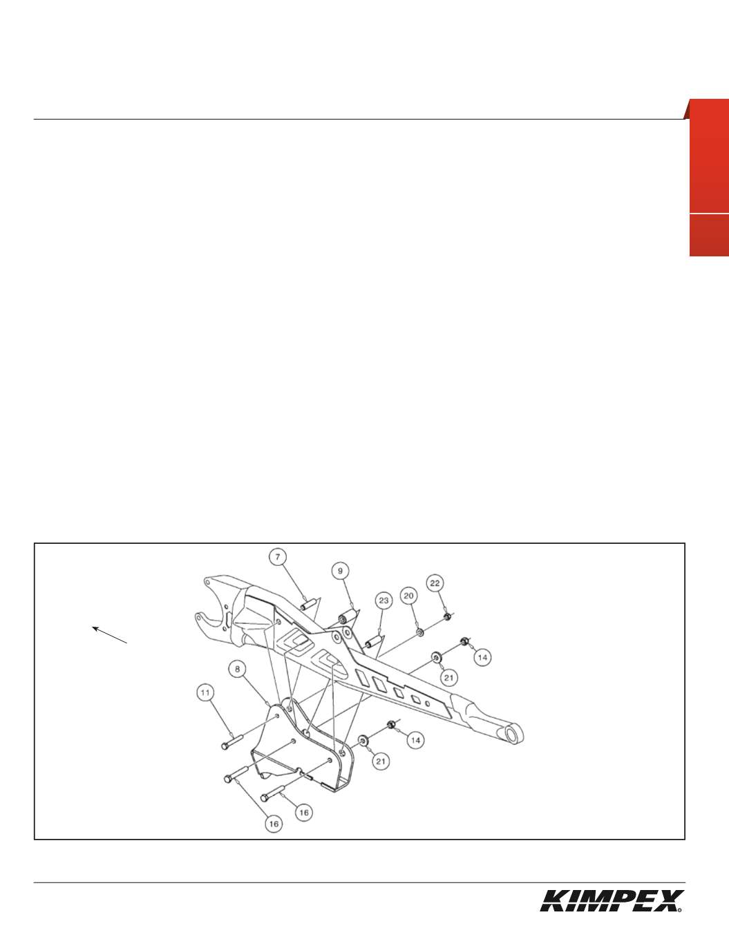
REAR A-ARM BRACKET INSTALLATION
(see sketch H)
WARNING:
Prior to installation, turn off the engine, put in two-wheel driving mode and the transmission in neutral, and
block the wheels.
1)
Raise the rear of the vehicle off the ground and remove the wheels.
WARNING:
When the vehicle is raised, make sure that it is properly secured/supported to prevent it from accidentally
falling during the installation of the A-arm brackets. If not properly secured/supported, serious physical injury could
occur.
IMPORTANT:
Do not invert the left and right A-arm brackets. The anti-rotation tube must be installed outside of the
suspension arm of the vehicle.
2)
Place the rear left A-arm bracket (#
8
) below the rear A-arm so that the rear upper mounting hole of the A-arm bracket is aligned with
that of the A-arm as shown.
3)
Fasten the rear part of the left A-arm bracket (#
8
) onto the A-arm using a
5/16” nc X 2-1/2”
hex bolt (#
11
), the rear tightening sleeve (#
7
),
a
5/16” dia
flat washer (#
20
), and a
5/16” nc
self-locking nut (#
22
) (finger tighten at this time).
4)
Fasten the middle part of the left A-arm bracket (#
8
) onto the A-arm using a
3/8” nc X 2-3/4”
hex bolt (#
16
), the middle tightening sleeve
(#
9
), a
10 mm I.D. X 25 mm O.D. X 4 mm
flat washer (#
21
), and a
3/8” nc
self-locking nut (#
14
) (finger tighten at this time).
5)
Fasten the front part of the left A-arm bracket (#
8
) onto the A-arm using a
3/8” nc X 2-3/4”
hex bolt (#
16
), the front tightening sleeve (#
23
),
a
10 mm I.D. X 25 mm O.D. X 4 mm
flat washer (#
21
), and a
3/8” nc
self-locking nut (#
14
).
6)
Torque the 3/8" nc bolts to 20 ft-lbs and the 5/16" nc bolt to 11 ft-lbs.
IMPORTANT:
Tighten in a manner not to permanently deform the assembly.
7)
Repeat
steps 2
to
6
for the opposite side.
sketch H
LEFT
REAR VIEW
Rear of
the ATV


