8/11
ATV
KIMPEX INC.
/ 5355, rue St-Roch / Drummondville (Québec) Canada / J2B 6V4
KIMPEX USA
/ 100 Walnut Street / Champlain, New York / 12919
Lithographié au Canada / Litho’d in Canada
2810418
A-2810418
FRONT AND REAR A-ARM BRACKET KIT
Kimpex
#
375121
For Commander WIDE TRACK, WTX, and TREX Track Kits
MOUNTING INSTRUCTIONS
8
(FOR OUTLANDER MAX MODEL ONLY)
MOUNT PLATE INSTALLATION
WARNING:
Prior to installation, turn off the engine, put
in two-wheel driving mode, and block the wheels.
WARNING:
When the ATV is raised, make sure that it is
properly secured/supported to prevent it fromaccidentally
falling during the installation of the A-arm brackets. If
not properly secured/supported, serious physical injury
could occur.
NOTE:
If your vehicle have no rear protective plate, go
to step 3.
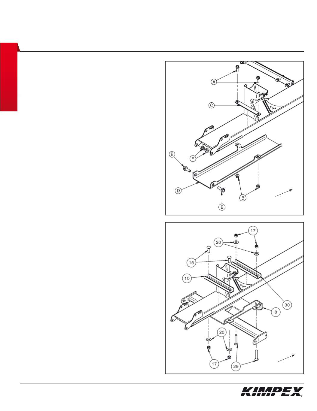
1)
Remove the original bolts (
A
) and nuts (
B
) retaining the bracket
(
C
) to the protective plate (
D
) (
see sketch J
).
2)
Remove the original bolts (
E
) and nuts (
F
) retaining the rear part
of the protective plate (
D
) to frame (
see sketch J
).
Do not discard. They will be reinstalled later.
3)
Fasten the front part of the mount plate (#
8
) to frame using the
front mount plate support (#
30
),
(2) 3/8” nc X 2-1/4”
carriage bolts
(#
29
),
(2) 3/8" dia
flat washers (#
20
), and
(2) 3/8” nc
self-locking nuts
(screw the first threads only) (
see sketch K
).
4)
Fasten the rear part of the mount plate (#
8
) to frame using the
rear mount plate support (#
10
),
(2) 3/8” nc X 1-1/4”
carriage bolts
(#
15
),
(2) 3/8" dia
flat washers (#
20
), and
(2) 3/8” nc
self-locking nuts
(#
17
) (
see sketch K
).
5)
Secure all bolts and nuts.
• TO FINISH THE INSTALLATION OF “COMMANDER
WIDE TRACK AND WTX” MODELS, SEE PAGE 9.
• TO FINISH THE INSTALLATION OF “COMMANDER
TREX” MODELS, SEE PAGE 10.
sketch J
sketch K
Front of the ATV
Front of the ATV


