2810324
KIMPEX INC.
/ 5355, rue St-Roch / Drummondville (Québec) Canada / J2B 6V4
KIMPEX USA
/ 100 Walnut Street / Champlain, New York / 12919
Lithographié au Canada / Litho’d in Canada
A-2810324 Rév. A
ATV
MOUNTING INSTRUCTIONS
FRONT AND REAR A-ARM BRACKET KIT
Kimpex
# 375117
FOR " COMMANDER WIDE TRACK " AND " COMMANDER TREK " / BRP OUTLANDER, OUTLANDER MAX
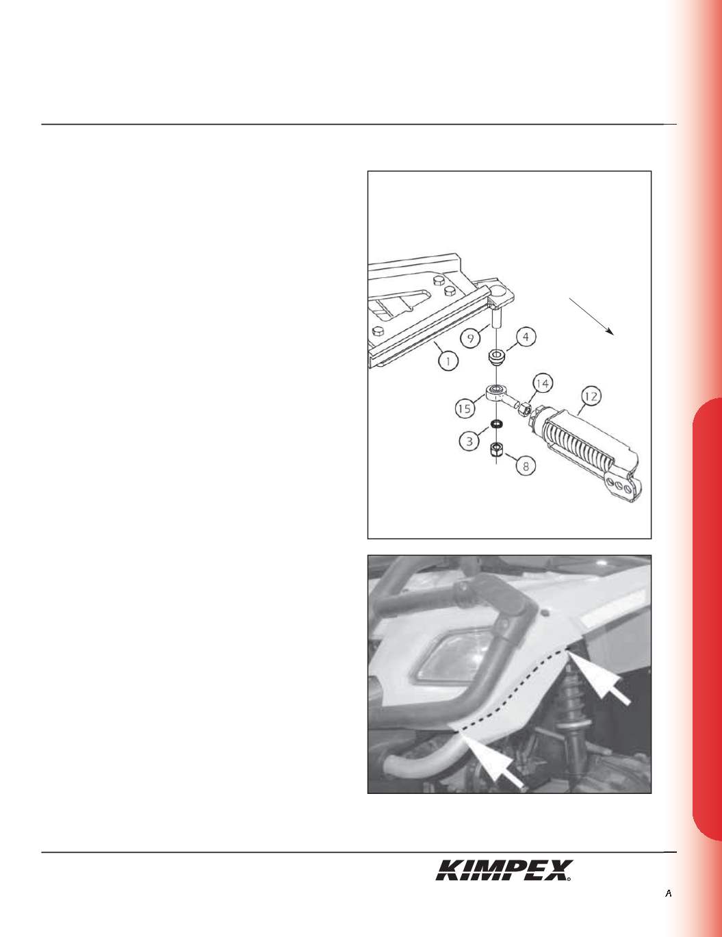
sketch E
sketch F
LEFT
FRONT VIEW
FRONT ANTI-ROTATION INSTALLATION
(see sketch E)
NOTE:
Pay special attention to the orientation given to
spacers (#3 and #4) during installation.
1)
Assemble the ball joint (#
15
) and the
1/2” nf
nut (#
14
) to the
front anti-rotation assembly (#
12
).
2)
Install the large ball joint spacer (#
4
) with the narrow part facing
down onto the
1/2” nc X 2-1/2”
carriage bolt (#
9
) installed in
step
3 of the “FRONT A-ARM BRACKET INSTALLATION”
section.
3)
Install the ball joint of the front anti-rotation assembly (#
15
) onto
the bolt (#
9
), below the large ball joint spacer (#
4
). Install the
short ball joint spacer (#
3
) with the narrow part facing up,
below the anti-rotation assembly (#
15
).
4)
Tighten the assembly with the
1/2” nc
self-locking nut (#
8
).
Torque to 55 ft-lbs.
WARNING:
If the bolts are not sufficiently tightened,
there is a risk of them becoming loose, of parts detaching
and risk of loss of control over the vehicle, as well as risk
of personal injury.
5)
Rotate the anti-rotation assembly (#
12
) towards the center of
the ATV to prevent it from interfering with the installation of the
Track Kit.
NOTE:
Refer to the Track Kit manual for the correct
adjustment.
6)
Repeat
steps 1
to
5
for the opposite side.
NOTE:
Under extreme conditions of use of the Track Kit,
it is possible that the tracks come into contact with the
plastics of the vehicle. It is then recommended to cut the
edge of the front fender as shown (see sketch F).
Front of
the ATV
5/9


