2810324
KIMPEX INC.
/ 5355, rue St-Roch / Drummondville (Québec) Canada / J2B 6V4
KIMPEX USA
/ 100 Walnut Street / Champlain, New York / 12919
Lithographié au Canada / Litho’d in Canada
A-2810324 Rév. A
ATV
MOUNTING INSTRUCTIONS
FRONT AND REAR A-ARM BRACKET KIT
Kimpex
# 375117
FOR " COMMANDER WIDE TRACK " AND " COMMANDER TREK " / BRP OUTLANDER, OUTLANDER MAX
“COMMANDER WIDE TRACK” / REAR
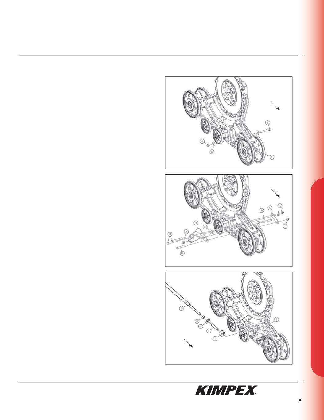
ANTI-ROTATION ARM BRACKET INSTALLATION
(see sketch J)
1)
Remove the interior wheel of the tensioner. Refer to the Track Kit
manual on section “
Wheels mounted on steel axles
”.
2)
Unscrew the self-locking nut (#
A
) from the 1/2” nc X 6” hex bolt
(#
B
) retaining the wheel closer to the adjustment slide (#
C
).
Remove and discard the flat washer (#
D
).
(see sketch K)
3)
Assemble the rear right anti-rotation arm bracket (#
3
) into the
hole made for this purpose in the plastic frame of the Track Kit
using
(3) 3/8” nc X 3-1/2”
hex bolts (#
14
), a
3/8” I.D. X 1-1/4” O.D. X .120”
Fender washer (#
23
), the rear anti-rotation arm clamping plate
(#
5
),
(3) 3/8” nc
self-locking nuts (#
17
), and the original self-
locking nut (#
A
) removed in
step 2
.
4)
Reinstall the interior wheel of the tensioner. Refer to the Track Kit
manual on section “
Wheels mounted on steel axles
”.
5)
Repeat
steps 1
to
4
for the opposite side.
“COMMANDER WIDE TRACK” / REAR ANTI-ROTATION
INSTALLATION (see sketch L)
WARNING:
Prior to installation, turn off the engine, put
in two-wheel driving mode, and block the wheels.
1)
Raise the rear of the ATV off the ground and remove the wheels.
WARNING:
When the ATV is raised, make sure that it is
properly secured/supported to prevent it from
accidentally falling during the installation. If not properly
secured/ supported, serious physical injury could occur.
2)
Screw the
5/8” nc
nut (#
16
) onto the threaded part of the anti-
rotation arm (#
9
).
3)
Install the
17mm I.D. X 50mm O.D. X 3mm
flat washer (#
22
) and the
bushing spacer tube (#
2
) onto the threaded part of the anti-
rotation arm (#
9
).
4)
Install the rubber bushing (#
1
) over the bushing spacer tube
(#
2
).
5)
Slide the anti-rotation arm assembly into the hole of the rear
right anti-rotation arm bracket (#
3
).
sketch J
sketch K
sketch L
RIGHT
REAR
VIEW
RIGHT
REAR VIEW
RIGHT
REAR VIEW
Rear of
the ATV
Rear of
the ATV
Rear of
the ATV
7/9


