KIMPEX INC.
/ 5355, rue St-Roch / Drummondville (Québec) Canada / J2B 6V4
KIMPEX USA
/ 100 Walnut Street / Champlain, New York / 12919
Lithographié au Canada / Litho’d in Canada
A-2810237 (F-00)
2810237
7/9
ATV
MOUNTING INSTRUCTIONS
FRONT AND REAR A-ARM BRACKET KIT
Kimpex
# 373718
For "Commander Wide Track" and " Commander trek Track kit
Yamaha Grizzly 700 2007-2008
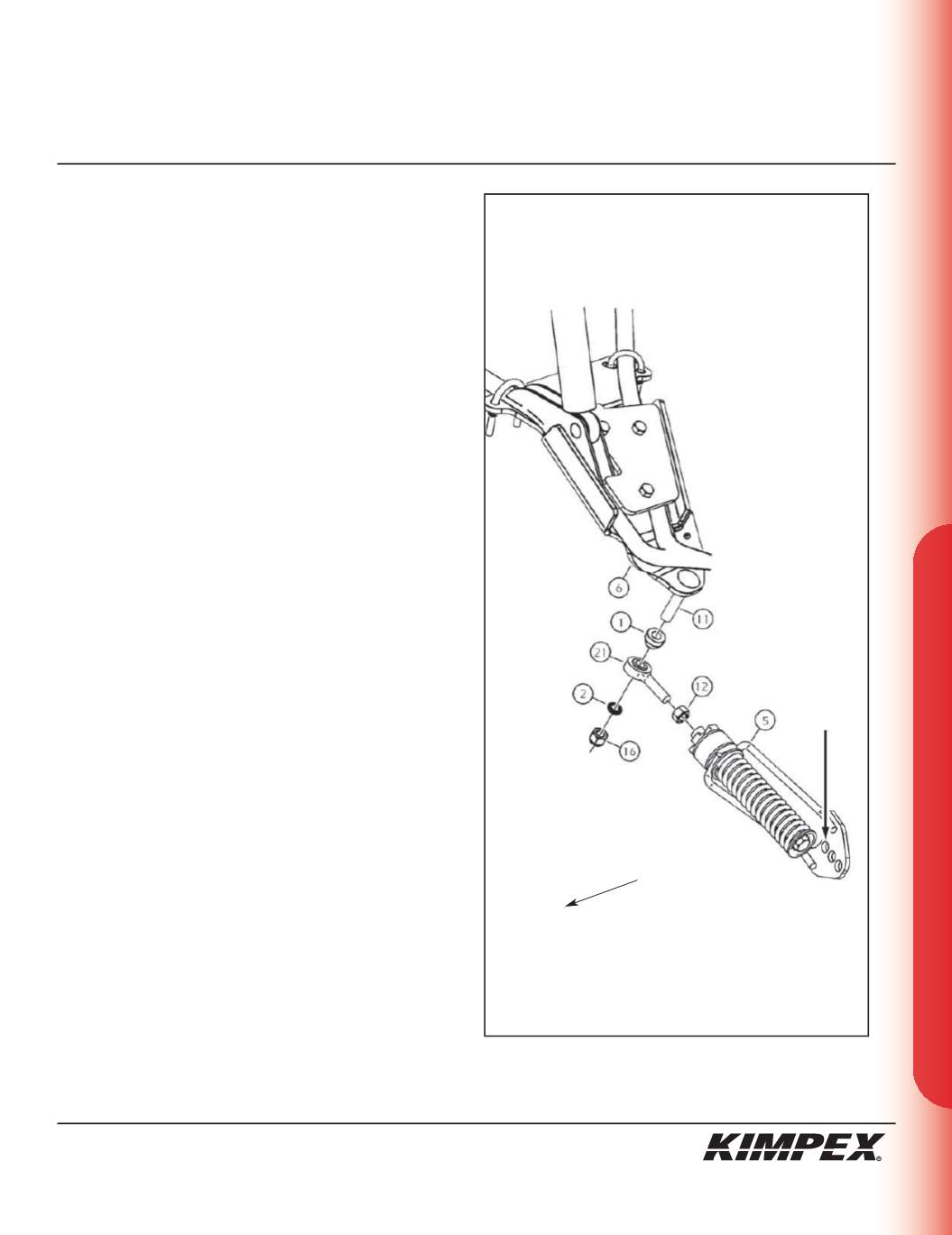
sketch G
LEFT
FRONT VIEW
FRONT ANTI-ROTATION INSTALLATION
(see sketch G)
NOTE :
Pay special attention to the orientation given to
spacers (#1 and #2) during installation.
1)
Assemble the ball joint (#
21
) and the
1/2” nf
nut (#
12
) to the
front anti-rotation assembly (#
5
)
.
2)
Install the large ball joint spacer (#
1
) with the narrow part facing
down onto the
1/2” nc X 2-1/2”
carriage bolt (#
11
) installed in
step
3 of the “FRONT A-ARM BRACKET INSTALLATION”
section.
3)
Install the ball joint of the front anti-rotation assembly (#
21
) onto
the bolt (#
11
), below the large ball joint spacer (#
1
). Install the
short ball joint spacer (#
2
) with the narrow part facing up,
below the anti-rotation assembly (#
21
).
4)
Tighten the assembly with the
1/2” nc
self-locking nut (#
16
).
Torque to 55 ft-lbs.
WARNING :
If the bolts are not sufficiently tightened,
there is a risk of them becoming loose, of parts detaching
and risk of loss of control over the vehicle, as well as risk
of personal injury.
5)
Rotate the anti-rotation assembly (#
5
) towards the center of the
ATV to prevent it from interfering with the installation of the
Track Kit.
NOTE :
Refer to the Track Kit manual for the correct
adjustment.
6)
Repeat
steps 1
to
5
for the opposite side.
IMPORTANT :
Make sure to use the correct mounting
hole on the anti-rotation (#5) when you assemble to the
Track Kit (see sketch G).
Front of
the ATV
MOUNTING
HOLE


