8/10
ATV
INSTALLATION MANUAL
FRONT AND REAR MOUNTING BRACKET KIT
KIMPEX N
o
374450
FOR COMMANDER TRACK KIT SYSTEM AND POLARIS RANGER XP 900 (2013 AND FURTHER) VEHICLES
KIMPEX INC.
/ 5355, rue St-Roch / Drummondville (Québec) Canada / J2B 6V4
KIMPEX USA
/ 100 Walnut Street / Champlain (New York) / 12919
Lithographié au Canada / Litho’d in Canada
•
2810478
•
A-2810478-EN
8
Installation of the front A-arm brackets
WARNING
1.
The vehicle must be
immobilized
and the
engine turned off
and cooled.
2.
Always wear
safety glasses
during installation, adjustment or repair.
3.
Please read and ensure you
have understood the warnings
and guidelines.
4.
Make sure the vehicle is
safely secured in place
by a system dedicated to this use (jack stands and hoist) and that it is supported or
fixed on locations that are not likely to break, bend or slip. A hydraulic jack is not safe; nor is a log. The vehicle must be not able to move.
The installation requires that the vehicle is in two-wheel drive mode with the gearbox in neutral. After lifting the vehicle
and removing the wheels:
1) Remove the universal joint guard. Keep parts for later
reinstallation.
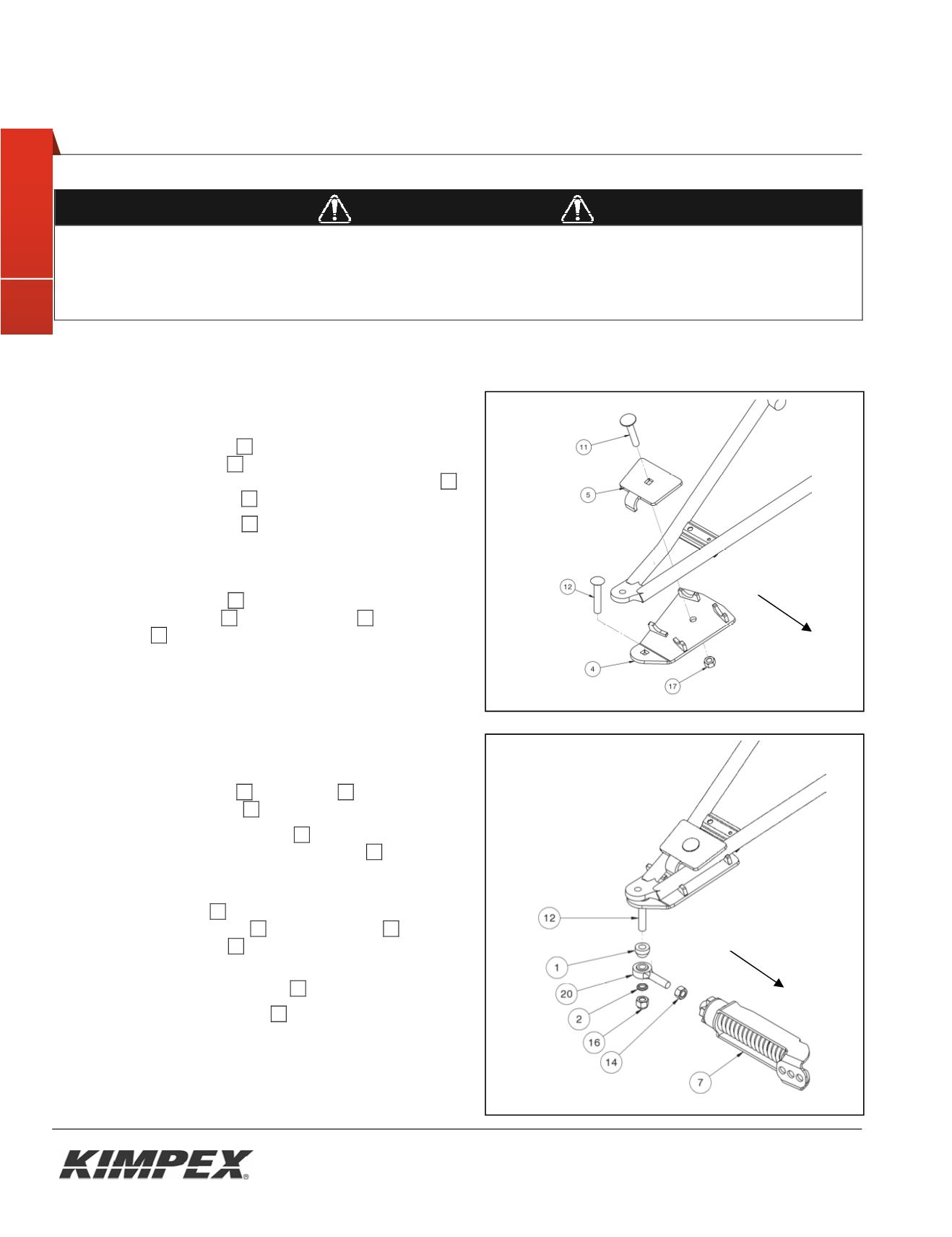
2) Insert the carriage bolt
12
in the hole identified by a label
on the A-arm bracket
04
. See
figure 7.
In the packaging, this bolt is mounted on the rod end
20
of the anti-rotation arm
07
. See
figure 8
3) Lean the A-arm bracket
04
under the front lower
suspension arm taking care that the suspension table
tubes are firmly pressed down on the half-moon brackets
of the A-arm bracket. See
figure 7.
4) Fix the A-arm bracket
04
to the suspension arm using
front clamping plate
05
, the carriage bolt
11
and the
nylon nut
17
.
5) Ensure that the A-arm bracket is well positioned in the
half-moon brackets and tighten all nuts in place.
Installation of the front anti-rotation arm
1) Assemble the ball joint
20
and the nut
14
to the anti-
rotation arm assembled
07
. See
figure 8.
2) Insert the large ball joint spacer
01
(with the tapered part
pointing downwards) on the carriage bolt
12
(Inserted in
step 2 of the section "Installation of the front A-arm
brackets").
Figure 8
3) Insert the ball joint
20
of the anti-rotation arm assembled
after the ball joint spacer
01
into the hex bolt
12
. Insert the
short ball joint spacer
02
below with the tapered side up.
Figure 8
4) Tighten all using the nylon nut
16
. Torque to 65 ft-lbs.
5) Rotate the anti-rotation arm
07
inwardly of the vehicle to
prevent it interfere with the installation of the track kit
system.
6) Repeat
steps 1
to
5
for the opposite side.
Fig. 7
Front of the UTV
Fig. 8
Front of the UTV


