5/6
ATV
MANUEL D’INSTALLATION
FRONT AND REAR MOUNTING BRACKET KIT
KIMPEX N
°
375906
FOR COMMANDER TRACK SYSTEM AND OUTLANDER 2012 VEHICLE
KIMPEX INC.
/ 5355, rue St-Roch / Drummondville (Québec) Canada / J2B 6V4
KIMPEX USA
/ 100 Walnut Street / Champlain (New York) / 12919
2810490
•
A-2810490-EN
•
Lithographié au Canada / Litho’d in Canada
5
Mount plate installation
WARNING
1.
The vehicle must be
immobilized
and the
engine turned off
and cooled.
2.
Always wear
safety glasses
during installation, adjustment or repair.
3.
Please read and ensure you
have understood the warnings
and guidelines.
4.
Make sure the vehicle is
safely secured in place
by a system dedicated to this use (jack stands and hoist) and that it is supported or
fixed on locations that are not likely to break, bend or slip. A hydraulic jack is not safe; nor is a log. The vehicle must be not able to move.
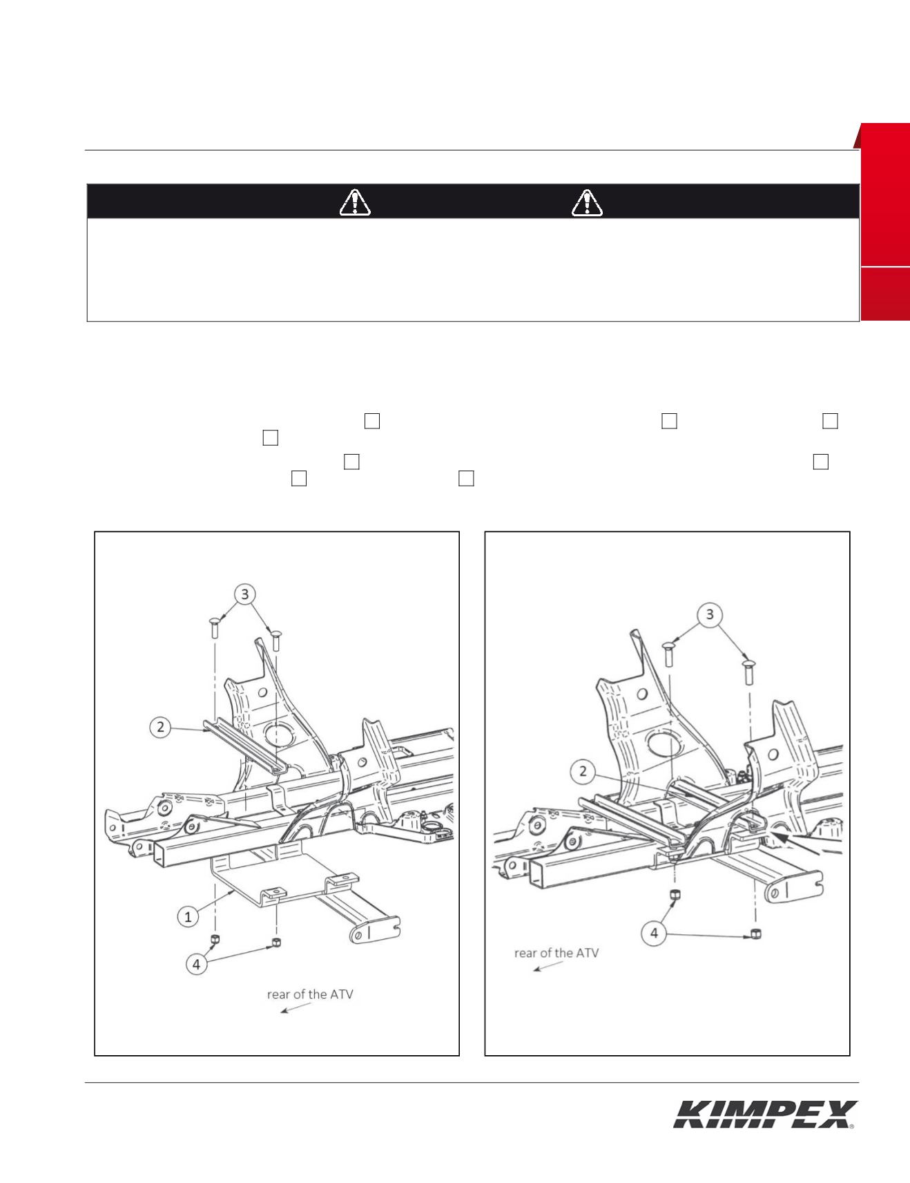
The installation requires that the vehicle is in two-wheel drive mode with the gearbox in neutral. After lifting the vehicle
and removing the wheels:
1) Fasten the rear part of the mount plate
01
to frame using one (1) mount plate support
02
, two (2) carriage bolts
03
and two (2) nylon nuts
04
(finger tighten at this time). See
figure 4.
2) Slide the other mount plate support
02
into the opening of the frame. Fasten the front part of the mount plate
01
using two (2) carriage bolts
03
and two (2) nylon nuts
04
. See
figure 5.
3) Secure all bolts and nuts.
Fig. 4
Fig. 5
I STA LATION M NUAL
FRONT AND REAR MOUNTING BRACKET KIT
KIMPEX N
°
375901
FOR CO MANDER TRACK YSTEM AND SPORTSMAN XP VE ICLE
KIMPEX INC.
/ 5355, rue St-Roch / Drummondville (Québec) Canada / J2B 6V4
KIMPEX USA
/ 100 Walnut Street / Champlain (New York) / 12919
Lithographié au Canada / Litho’d in Canada
•
2810484
•
A-2810484-EN
4
Rear susp nsion brackets installation
WARNING
1.
Th vehicle must be
i mobilized
and the
engine turned off
and cooled.
2.
Always wear
safety glas es
during inst llation, adjustment or repair.
3.
Pleas re d and ensure you
have understood the war ings
and guidelines.
4.
Make sure th vehicle is
safely secured in place
by a system edicated o thi use (jack stands and hoist) and that it is supported or
fixed on locations th t are not likely to break, bend or slip. A hydraulic jack is not safe; nor is a log. Th vehicle must be not able to move.
The inst llation requires that the vehicle is in two-wheel drive mode wit the gearbox i neutral. After lifting the vehicle
and removing the wheels:
1) Inser the rear suspension bracket
01
into the suspension table of the vehicle, by sliding i in the di ection indicated
by the
figure 4A
by
arrows 1 and 2.
2) After making sure that the front support bracket is well positioned under the suspension table tube, fix the rear
suspension bracket
01
using the U-bolt
02
, the flat washer
04
(place the washer in the oblong hole side) and the two
(2) nylon nuts
03
. See
figure 4B
.
3) Tighten all bolts in place.
WARNING
1.
Do not overtorque the bolts
. Some parts may be subject to deformations. If the bolts are too tight, safety aspects could be compromised.
2.
Be careful: an incorrectly positioned Suspension bracket could give some play, which could make driving riskier as well as lead to
breakage to the vehicle, a loss of control and serious injuries.
A
Fig. 4
B


