6/7
MANUEL D’INSTALLATION
FRONT AND REAR MOUNTING BRACKET KIT
KIMPEX N
°
375907
FOR COMMANDER TRACK SYSTEM AND OUTLANDER 2012 – OUTLANDER MAX 2013 VEHICLES
KIMPEX INC.
/ 5355, rue St-Roch / Drummondville (Québec) Canada / J2B 6V4
KIMPEX USA
/ 100 Walnut Street / Champlain (New York) / 12919
Lithographié au Canada / Litho’d in Canada
•
2810491
•
A-2810491-EN
6
Mount plate installation (for outlander max model only)
WARNING
1.
The vehicle must be
immobilized
and the
engine turned off
and cooled.
2.
Always wear
safety glasses
during installation, adjustment or repair.
3.
Please read and ensure you
have understood the warnings
and guidelines.
4.
Make sure the vehicle is
safely secured in place
by a system dedicated to this use (jack stands and hoist) and that it is supported or
fixed on locations that are not likely to break, bend or slip. A hydraulic jack is not safe; nor is a log. The vehicle must be not able to
move.
The installation requires that the vehicle is in two-wheel drive mode
with the gearbox in neutral. After lifting the vehicle and removing the
wheels:
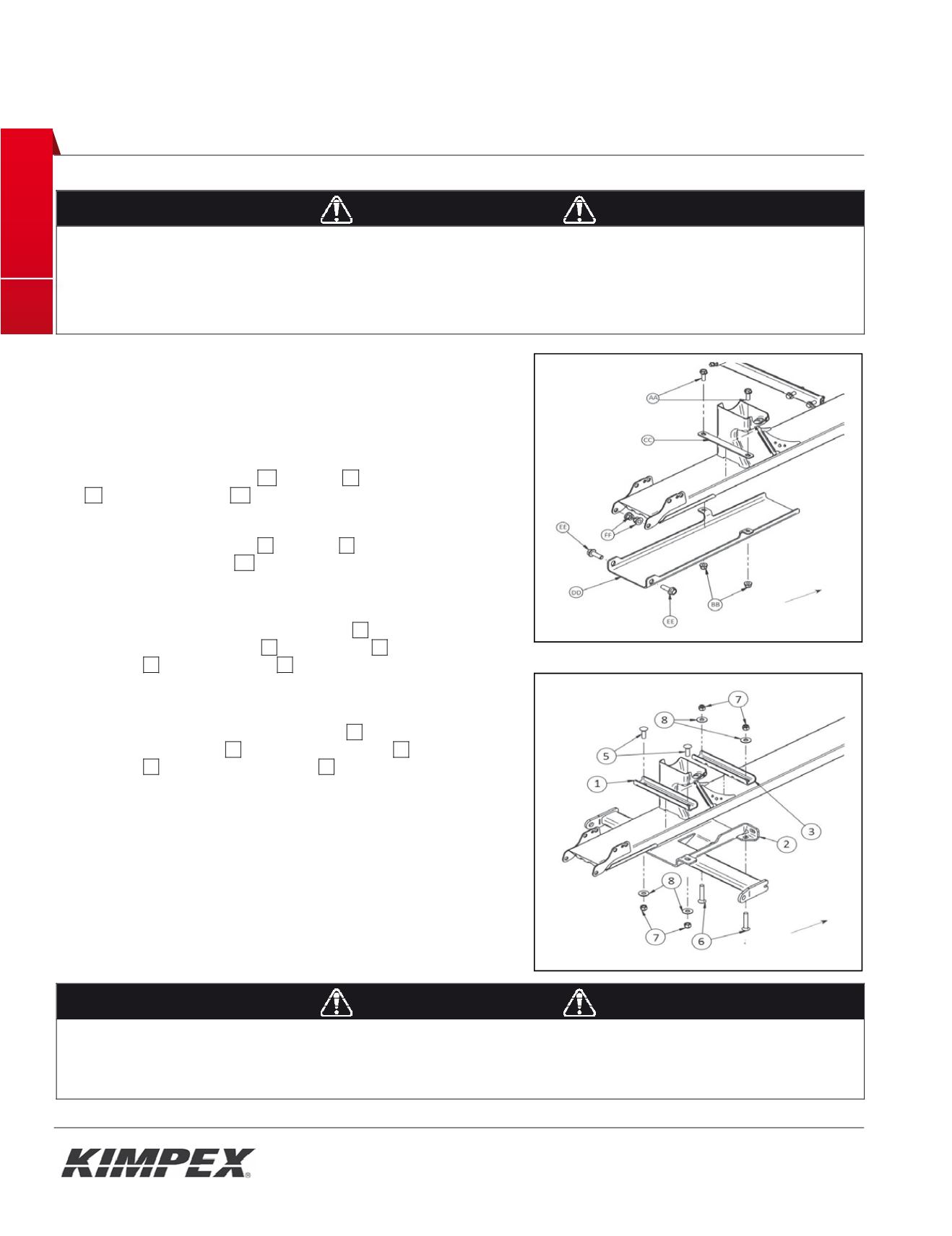
NOTE: If your vehicle have no rear protective plate, go to step 3.
1) Remove the original bolts
AA
and nuts
BB
retaining the bracket
CC
to protective plate
DD
. See
Figure 7.
2) Remove the original bolts
EE
and nuts
FF
retaining the rear part
of the protective plate
DD
to frame. Do not discard, they will be
reinstalled later. See
Figure 7.
3) Fasten the front part of the mount plate
02
to frame using the
front mount plate support
03
, two (2) bolts
06
, two (2) flat
washers
08
and two (2) nuts
07
(finger tighten at this time). See
figure 8.
4) Fasten the rear part of the mount plate
02
to frame using the rear
mount plate support
01
, two (2) carriage bolts
05
, two (2) flat
washers
08
and two (2) nylon nuts
07
. See
figure 8
.
5) Secure all bolts and nuts.
WARNING
1.
Do not overtorque the bolts. Some parts may be subject to deformation. If the bolts are too tight, some safety aspects could be
compromised.
2.
Be careful: an incorrectly positioned A-arm bracket could give some play, which could make driving riskier as well as lead to breakage to
the vehicle, a loss of control and serious injuries..
Fig. 7
Front of the ATV
Fig. 8
Front of the ATV
INSTAL ATION MANUAL
I
I
I
°
1
F R C
ER TR SYSTE A SPORTSMAN XP VEHICLE
IMPEX INC.
/ 535 , rue St-Roch / Dru ondville (Québec) Canada / J2B 6V4
IMPEX US
/ 10 Walnut Stre t / Cha plain (Ne York) / 12919
Lithographié au Canada / Litho’d in Canada
•
2810484
•
A-2810484-EN
4
Rear sus ens on br ckets installation
I
1.
The vehicle must be
immobilized
and the
engine turned off
and cooled.
2.
Always wear
safety glasses
during installation, adjustment or repair.
3.
Please read and ensure you
have understood the warnings
and guidelines.
4.
Make sure the vehicle is
safely secured in place
by a system dedicated to this use (jack stands and hoist) and that it is supported or
fixed on locations that are not likely to break, bend or slip. A hydraulic jack is not safe; nor is a log. The vehicle must be not able to move.
The installation requires that the vehicle is in two-whe l drive mode with the gearbox in neutral. After lifting the vehicle
and removing the wheels:
1) Insert the rear suspension bracket
01
into the suspension table of the vehicle, by sliding it in the direction indicated
by the
figure 4A
by
arrows 1 and 2.
2) After making sure that the front support bracket is well positioned under the suspension table tube, fix the rear
suspension bracket
01
using the U-bolt
02
, the flat washer
04
(place the washer in the oblong hole side) and the two
(2) nylon nuts
03
. See
figure 4B
.
3) Tighten all bolts in place.
WARNING
1.
Do not overtorque the bolts
. Some parts may be subject to deformations. If the bolts are too tight, safety aspects could be compromised.
2.
Be careful: an incorrectly positioned Suspension bracket could give some play, which could make driving riskier as well as lead to
breakage to the vehicle, a loss of control and serious injuries.
A
Fig. 4
B


