2810293
KIMPEX INC.
/ 5355, rue St-Roch / Drummondville (Québec) Canada / J2B 6V4
KIMPEX USA
/ 100 Walnut Street / Champlain, New York / 12919
Lithographié au Canada / Litho’d in Canada
A-2810293
ATV
MOUNTING INSTRUCTIONS
FRONT AND REAR A-ARM BRACKET KIT
Kimpex
# 375115
FOR " COMMANDER WIDE TRACK " AND " COMMANDER TREK " / BRP OUTLANDER MAX
REAR A-ARM BRACKET INSTALLATION
WARNING :
Prior to installation, turn off the engine, put
in two-wheel driving mode, and block the wheels.
1)
Raise the rear of the ATV off the ground and remove the wheels.
WARNING :
When the ATV is raised, make sure that it is
properly secured/supported to prevent it from
accidentally falling during the installation of the sub-
tables. If not properly secured/supported, serious
physical injury could occur.
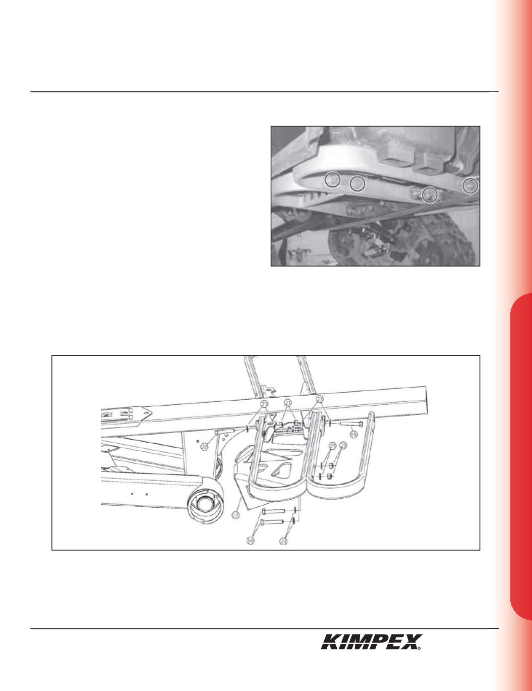
2)
Remove the original bolts and nuts retaining the footpeg to
frame (
see sketch G
).
3)
Position and fasten the rear left A-arm bracket (#
12
) below the footpeg of the vehicle using
(3) 5/16” nc X 2”
hex bolts (#
14
), a
5/16” nc X 1-
1/2”
hex bolt (#
27
),
(8) 5/16” dia
flat washers (#
23
), and
(4) 5/16” nc
self-locking nuts (#
21
) (
see sketch H
).
IMPORTANT :
Tighten in a manner not to permanently deform the assembly.
4)
Repeat
steps 2
and
3
for the opposite side.
t
TO FINISH THE INSTALLATION OF “COMMANDER WIDE TRACK” MODELS, SEE PAGES 9 AND 10.
t
TO FINISH THE INSTALLATION OF “COMMANDER TREK” MODELS, SEE PAGES 11 AND 12.
sketch G
sketch H
7/12


