2810293
KIMPEX INC.
/ 5355, rue St-Roch / Drummondville (Québec) Canada / J2B 6V4
KIMPEX USA
/ 100 Walnut Street / Champlain, New York / 12919
Lithographié au Canada / Litho’d in Canada
A-2810293
ATV
MOUNTING INSTRUCTIONS
FRONT AND REAR A-ARM BRACKET KIT
Kimpex
# 375115
FOR " COMMANDER WIDE TRACK " AND " COMMANDER TREK " / BRP OUTLANDER MAX
“COMMANDER WIDE TRACK” /
REAR FRAME BRACKET INSTALLATION
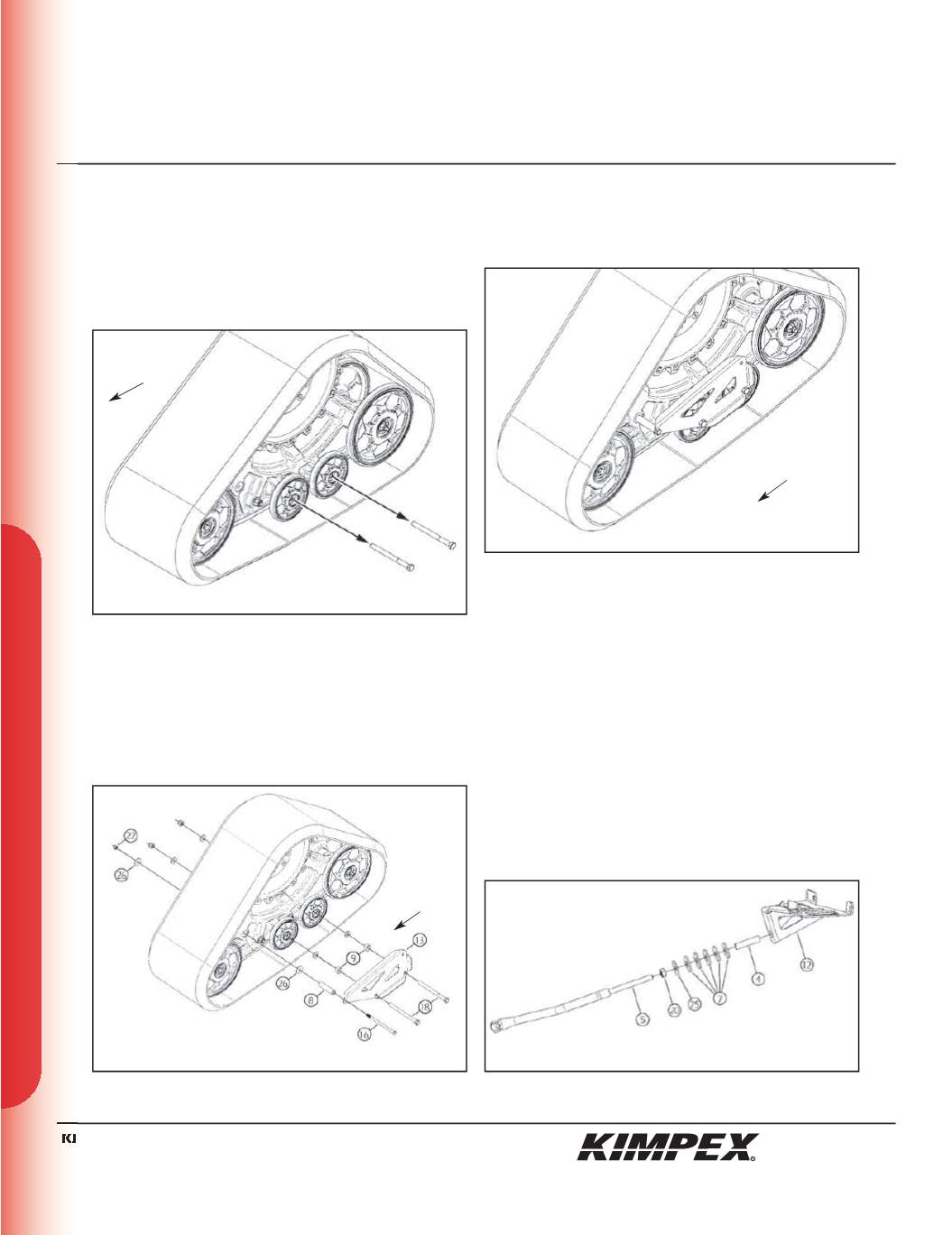
1)
Remove the two
1⁄2” nc
bolts retaining the small wheels
(5.66” dia) to the rear left frame of the Track Kit (
see sketch I
).
2)
Fasten the lower part of the rear left frame bracket (#
13
) to
frame using
(2) 1/2” nc X 6-1/2”
hex bolts (#
18
),
(2)
short spacers
(#
9
), and the flat washers and
1⁄2” nc
nuts removed in
step 1
(
see sketch J
).
Fasten the rear part of the rear left frame bracket (#
13
) to frame
using a
3/8” nc X 6-1/2”
hex bolt (#
16
), a long spacer (#
8
),
(2)
3/8” I.D. X 1-1/4” O.D. X .120”
Fender washers (#
26
), and a
3/8” nc
self-locking nut (#
22
) (
see sketch J
).
3)
Torque the wheel nuts to 30 ft-lbs (40 Nm) and the nut (#
22
) to
16 ft-lbs (22 Nm) (
see sketch K
).
4)
Repeat
steps 1
and
4
for the opposite side.
NOTE :
Refer to the Track Kit manual for the correct
adjustment.
IMPORTANT :
Do not install the rear anti-rotation tubes.
“COMMANDER WIDE TRACK” /
REAR ANTI-ROTATION INSTALLATION
(see sketch L)
1)
Screw the
5/8” nc
nut (#
20
) onto the threaded part of the anti-
rotation tube (#
5
).
2)
Install the
17mm I.D. X 50mm O.D. X 3mm
flat washer (#
25
), the
(5)
spacers (U.H.M.W.) (#
7
), and the spacer tube (#
4
) onto the
threaded part of the anti-rotation tube (#
5
).
3)
Slide the anti-rotation assembly into the hole on the bottom of
the rear A-arm bracket (#
12
).
sketch I
sketch J
sketch L
LEFT REAR VIEW
LEFT REAR VIEW
Rear of
the ATV
sketch K
LEFT REAR VIEW
Rear of
the ATV
Rear of
the ATV
8/12


