2810326
KIMPEX INC.
/ 5355, rue St-Roch / Drummondville (Québec) Canada / J2B 6V4
KIMPEX USA
/ 100 Walnut Street / Champlain, New York / 12919
Lithographié au Canada / Litho’d in Canada
A-2810326 Rév. A
ATV
MOUNTING INSTRUCTIONS
FRONT AND REAR A-ARM BRACKET KIT
Kimpex
# 375113
FOR " COMMANDER WIDE TRACK " AND " COMMANDER TREK " / BRP QUEST, TRAXTER
“COMMANDER TREK” / REAR ANTI-ROTATION
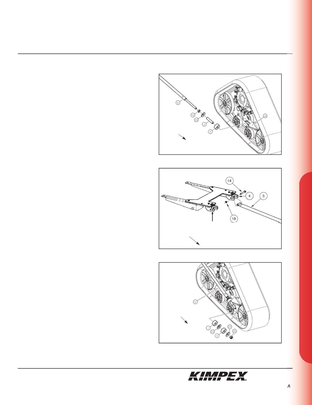
INSTALLATION (see sketch S)
1)
Screw the
5/8” nc
nut (#
16
) onto the threaded part of the anti-
rotation arm (#
5
).
2)
Install the
17mm I.D. X 50mm O.D. X 3mm
flat washer (#
23
) and the
bushing spacer tube (#
2
) onto the threaded part of the anti-
rotation arm (#
5
).
3)
Install the rubber bushing (#
1
) over the bushing spacer tube
(#
2
).
4)
Slide the anti-rotation arm assembly into the hole of the rear
right anti-rotation arm bracket (#
26
).
(see sketch T)
5)
Fasten the other end of the rear anti-rotation arm (#
5
) onto the
rear anti-rotation arm support (#
4
) installed in
step 2 at the
“SNOWPLOW ADAPTER INSTALLATION” section
using the
3/8” nc X 3”
hex bolt (#
14
) and the
3/8” nc
self-locking nut (#
19
).
(see sketch U)
6)
Install the rubber bushing (#
1
), the
3/4” I.D. X 2” O.D. X 1/8”
flat
washer (#
22
), and the other rubber bushing (#
1
) over the
bushing spacer tube (#
2
).
7)
Install the
17mm I.D. X 50mm O.D. X 3mm
flat washer (#
23
) onto the
threaded part of the anti-rotation arm (#
5
).
8)
Screw the
5/8” nc
self-locking nut (#
20
) onto the threaded part of
the anti-rotation arm (#
5
). Do not overtighten.
NOTE :
Refer to the Track Kit manual to complete the
installation.
9)
Repeat
steps 1
to
8
for the opposite side.
Rear of
the ATV
sketch S
sketch T
sketch U
RIGHT
REAR VIEW
RIGHT
REAR VIEW
Rear of
the ATV
Rear of
the ATV
MOUNTING
HOLE
11/11


