2810293
KIMPEX INC.
/ 5355, rue St-Roch / Drummondville (Québec) Canada / J2B 6V4
KIMPEX USA
/ 100 Walnut Street / Champlain, New York / 12919
Lithographié au Canada / Litho’d in Canada
A-2810293
ATV
MOUNTING INSTRUCTIONS
FRONT AND REAR A-ARM BRACKET KIT
Kimpex
# 375115
FOR " COMMANDER WIDE TRACK " AND " COMMANDER TREK " / BRP OUTLANDER MAX
3)
Screw the
5/8” nc
nut (#
20
) onto the threaded part of the anti-
rotation tube (#
5
) (
see sketch R
).
4)
Install the
17mm I.D. X 50mm O.D. X 3mm
flat washer (#
25
), the
(5)
spacers (U.H.M.W.) (#
7
), and the spacer tube (#
4
) onto the
threaded part of the anti-rotation tube (#
5
) (
see sketch R
).
5)
Slide the anti-rotation assembly into the hole on the bottom of
the rear A-arm bracket (#
12
) (
see sketch R
).
6)
Slide the outside (#
10
) and inside lock tubing (#
11
) into the
tube of the frame. Press firmly the stop ring of the outside lock
tubing (#
10
) on the frame’s tube end (
see sketch S
).
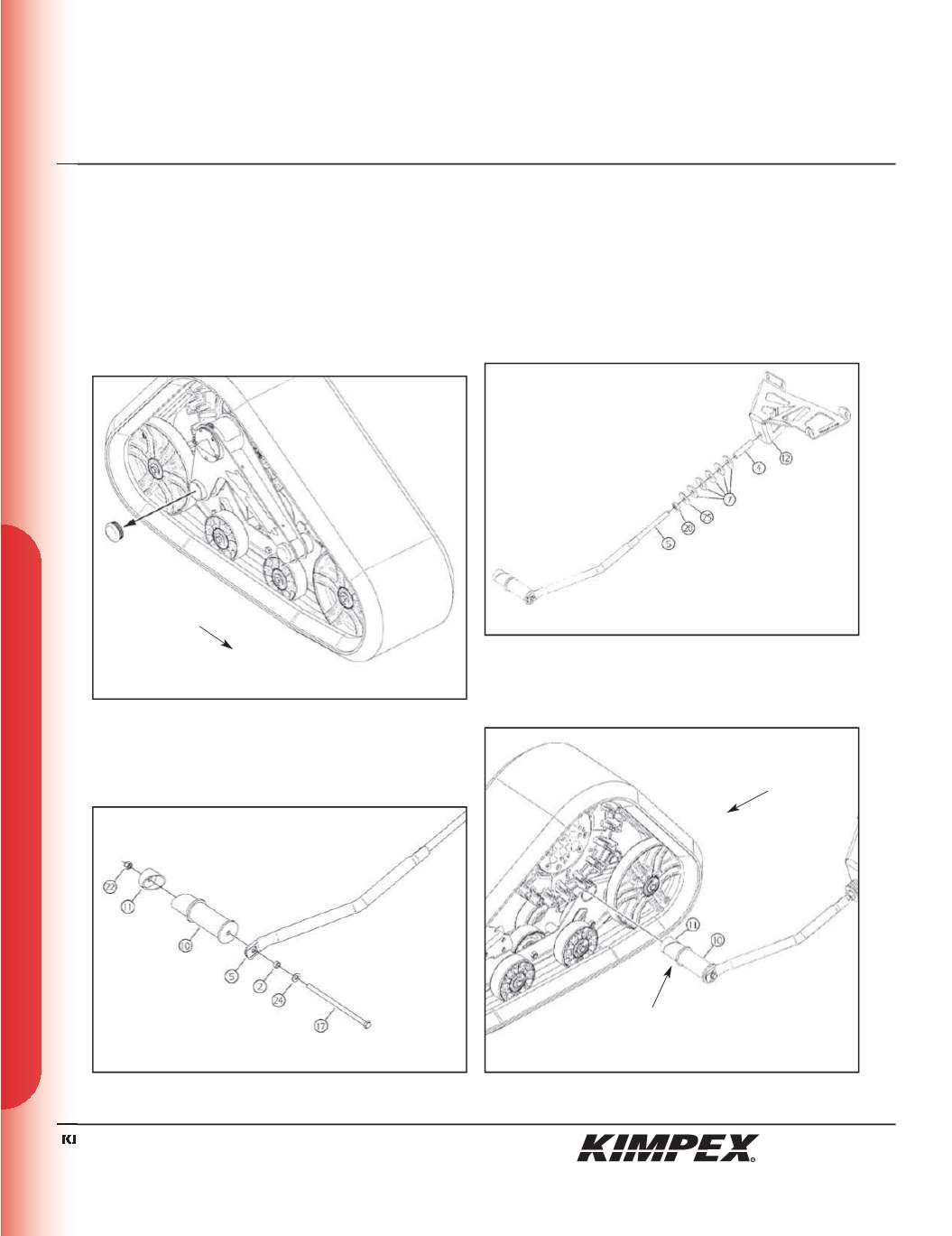
2)
Assemble the rear anti-rotation tube (#
5
) to the outside (#
10
) and
inside lock tubing (#
11
) using the
3/8” nc X 7-1/2”
hex bolt (#
17
), the
3/8” dia
flat washer (#
24
), the tightening spacer (#
2
), and the
3/8” nc
self-locking nut (#
22
) (
see sketch Q
). Finger tighten only
at this time.
«COMMANDER TREK» / REAR LOCK TUBING AND
ANTI-ROTATION INSTALLATION
NOTE :
Refer to the Track Kit manual for the correct
adjustment.
IMPORTANT :
Do not install the rear anti-rotation tubes.
1)
Remove the plastic cap from the rear left frame of the Track Kit
(
see sketch P
).
sketch P
LEFT REAR VIEW
Rear of
the ATV
sketch R
LEFT REAR VIEW
sketch Q
LEFT REAR VIEW
sketch S
LEFT REAR VIEW
Rear of
the ATV
stop ring
10/12


