2810294
KIMPEX INC.
/ 5355, rue St-Roch / Drummondville (Québec) Canada / J2B 6V4
KIMPEX USA
/ 100 Walnut Street / Champlain, New York / 12919
Lithographié au Canada / Litho’d in Canada
A-2810294 Rév. A
ATV
MOUNTING INSTRUCTIONS
FRONT AND REAR A-ARM BRACKET KIT
Kimpex
# 375116
FOR " COMMANDER WIDE TRACK " AND " COMMANDER TREK " / BRP RENEGADE
sketch E
LEFT
FRONT VIEW
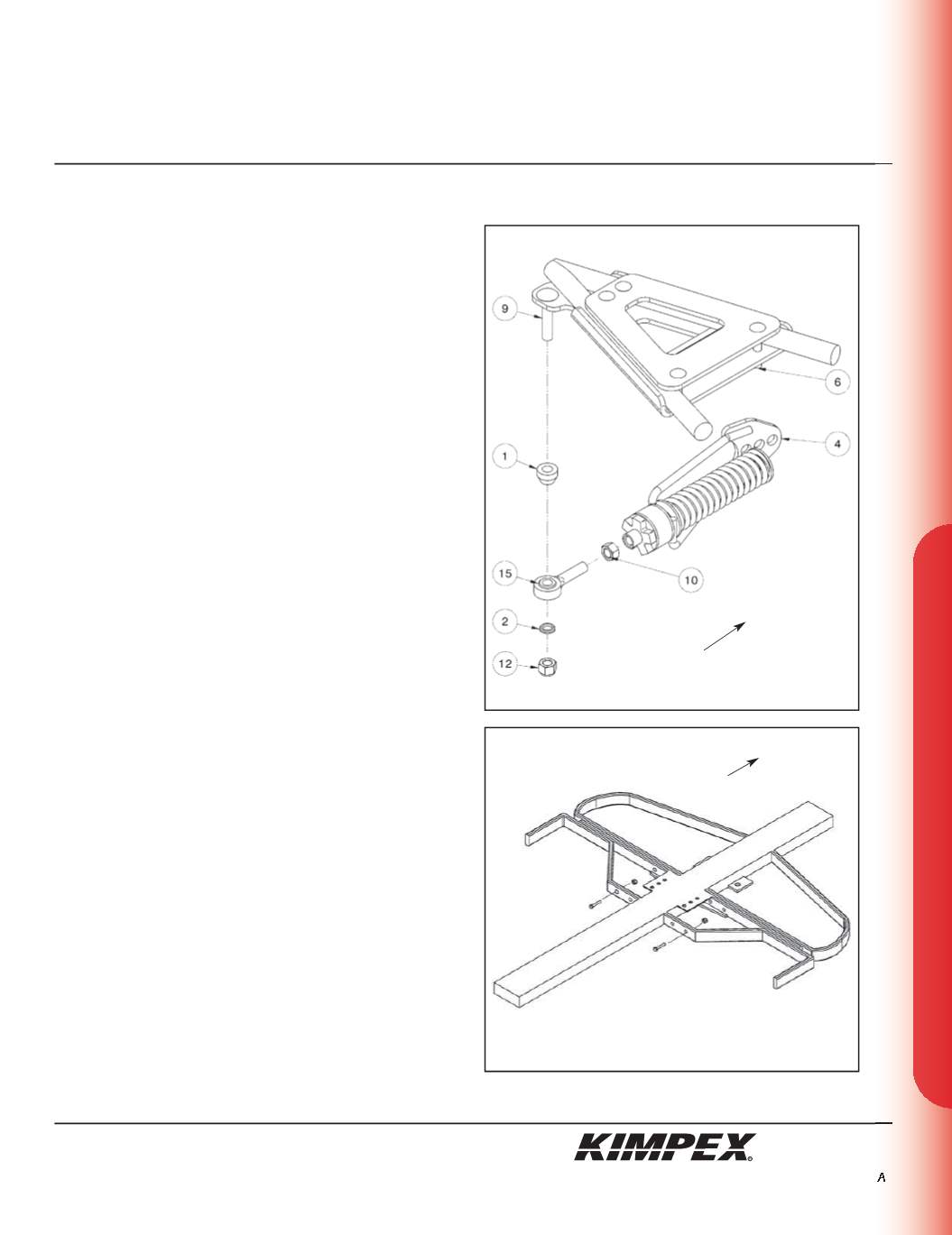
FRONT ANTI-ROTATION INSTALLATION
(see sketch E)
NOTE :
Pay special attention to the orientation given to
spacers (#1 and #2) during installation.
1)
Assemble the ball joint (#
15
) and the
1/2” nf
nut (#
10
) to the
front anti-rotation assembly (#
4
).
2)
Install the large ball joint spacer (#
1
) with the narrow part facing
down onto the
1/2” nc X 2-1/2”
carriage bolt (#
9
) installed in
step
3 of the “FRONT A-ARM BRACKET INSTALLATION”
section.
3)
Install the ball joint of the front anti-rotation assembly (#
15
) onto
the bolt (#
9
), below the large ball joint spacer (#
1
). Install the
short ball joint spacer (#
2
) with the narrow part facing up,
below the anti-rotation assembly (#
4
).
4)
Tighten the assembly with the
1/2” nc
self-locking nut (#
12
).
Torque to 55 ft-lbs.
WARNING :
If the bolts are not sufficiently tightened,
there is a risk of them becoming loose, of parts detaching
and risk of loss of control over the vehicle, as well as risk
of personal injury.
5)
Rotate the anti-rotation assembly (#
4
) towards the center of the
ATV to prevent it from interfering with the installation of the
Track Kit.
NOTE :
Refer to the Track Kit manual for the correct
adjustment.
6)
Repeat
steps 1
to
5
for the opposite side.
NOTE :
Under extreme conditions of use of the Track Kit,
it is possible that the tracks come into contact with the
plastics of the vehicle.
REAR A-ARM BRACKET INSTALLATION
WARNING :
Prior to installation, turn off the engine, put
in two-wheel driving mode, and block the wheels.
1)
Raise the rear of the ATV off the ground and remove the wheels.
WARNING :
When the ATV is raised, make sure that it is
properly secured/supported to prevent it from
accidentally falling during the installation of the sub-
tables. If not properly secured/supported, serious
physical injury could occur.
2)
Remove the original bolts and nuts retaining the footpegs to
frame (
see sketch F
).
Front of the ATV
sketch F
Front of the ATV
5/10


