7/8
ATV
KIMPEX INC.
/ 5355, rue St-Roch / Drummondville (Québec) Canada / J2B 6V4
KIMPEX USA
/ 100 Walnut Street / Champlain, New York / 12919
Lithographié au Canada / Litho’d in Canada
2810408
A-2810408
FRONT AND REAR A-ARM BRACKET KIT
Kimpex
#
374510
For Commander TREX UTV Track Kit
MOUNTING INSTRUCTIONS
7
sketch H
sketch G
LEFT
REAR
VIEW
Front of
the ATV
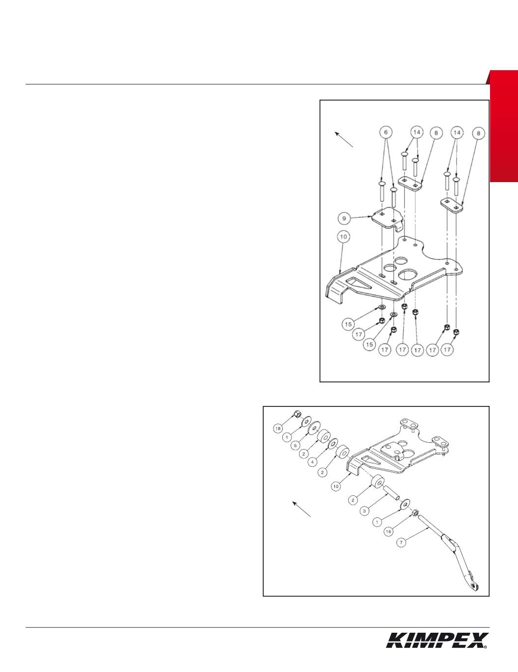
REAR A-ARM BRACKET INSTALLATION (see sketch G)
WARNING :
Prior to installation, turn off the engine, put in two-wheel
driving mode and the transmission in neutral, and block the wheels.
1)
Raise the rear of the vehicle off the ground and remove the wheels.
WARNING :
When the vehicle is raised, make sure that it is properly
secured/supported to prevent it from accidentally falling during the
installation of the A-arm brackets. If not properly secured/supported,
serious physical injury could occur.
2)
Remove the rear left CV shield. Do not discard. They will be reinstalled later.
3)
Place the rear left A-arm bracket (#
10
) below the rear lower A-arm so that the two
parts fit snugly.
4)
Install the
(2)
rear inner A-arm clamping plates (#
8
) above the lower A-arm and
fasten it to the A-arm bracket (#
10
) using the
(4) 3/8” nc X 2-1/4”
carriage bolts (#
14
)
and the
(4)
3/8” nc
self-locking nuts (#
17
).
Install the rear left outer A-arm clamping plate (#
9
) above the lower A-arm and
fasten it to the A-arm bracket (#
10
) using the
(2) 3/8” nc X 2-1/2”
carriage bolts (#
6
),
the
(2) 3/8” dia
flat washers (#
15
), and the
(2) 3/8” nc
self-locking nuts (#
17
).
Torque to 20 ft-lbs.
IMPORTANT :
Tighten in a manner not to permanently deform the
assembly.
5)
Repeat
steps 2
to
4
for the opposite side.
REAR ANTI-ROTATION INSTALLATION (see sketch H)
1)
Screw the
5/8” nc
nut (#
16
) onto the threaded part of the anti-rotation tube (#
7
).
2)
Install the
17mm I.D. X 50mm O.D. X 3mm
flat washer (#
1
) and the bushing spacer tube
(#
3
) onto the threaded part of the anti-rotation tube (#
7
).
3)
Install the rubber bushing (#
2
) over the bushing spacer tube (#
3
).
4)
Slide the anti-rotation assembly into the hole on the bottom of
the rear A-arm bracket (#
10
).
5)
Install the rubber bushing (#
2
), the
3/4” I.D. X 2” O.D. X 1/8”
flat
washer (#
4
), and the other rubber bushing (#
2
) over the
bushing spacer tube (#
3
).
6)
Install the support washer (#
5
) and the
17mm I.D. X 50mm O.D. X
3mm
flat washer (#
1
) onto the threaded part of the anti-rotation
tube (#
7
).
7)
Screw the
5/8” nc
self-locking nut (#
18
) onto the threaded part
of the anti-rotation tube (#
7
).
Do not overtighten.
NOTE :
Refer to the Track Kit manual to complete the
installation.
8)
Repeat
steps 1
to
7
for the opposite side.
LEFT
REAR VIEW
Front of
the ATV


