2810193
KIMPEX INC.
/ 5355, rue St-Roch / Drummondville (Québec) Canada / J2B 6V4
KIMPEX USA
/ 100 Walnut Street / Champlain, New York / 12919
Lithographié au Canada / Litho’d in Canada
A-2810193 (F-00) Rév. A
7/7
MOUNTING INSTRUCTIONS
FRONT AND REAR A-ARM BRACKET KIT
Kimpex
# 373111
FOR " COMMANDER " TRACK KIT / BRP OUTLANDER
ATV
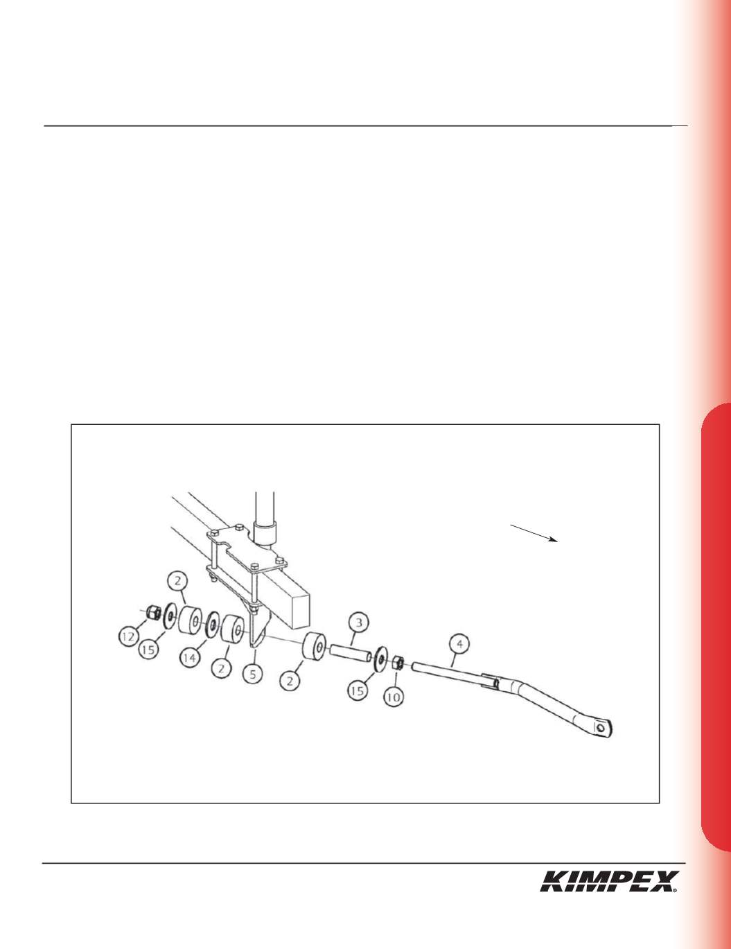
REAR ANTI-ROTATION INSTALLATION
(see sketch F)
1)
Screw the
5/8” nc
nut (#
10
) onto the threaded part of the anti-rotation tube (#
4
).
2)
Install the
17mm I.D. X 50mm O.D. X 3mm
flat washer (#
15
) and the bushing spacer tube (#
3
) onto the threaded part of the anti-rotation
tube (#
4
).
3)
Install the rubber bushing (#
2
) over the bushing spacer tube (#
3
).
4)
Slide the anti-rotation assembly into the hole on the bottom of the rear left sub-table plate (#
5
).
5)
Install the rubber bushing (#
2
), the
3/4” I.D. X 2” O.D. X 1/8”
flat washer (#
14
), and the other rubber bushing (#
2
) over the bushing spacer
tube (#
3
).
6)
Install the
17mm I.D. X 50mm O.D. X 3mm
flat washer (#
15
) onto the threaded part of the anti-rotation tube (#
4
).
7)
Screw the
5/8” nc
self-locking nut (#
12
) onto the threaded part of the anti-rotation tube (#
4
). Do not overtighten.
NOTE :
Refer to the track kit manual for the correct adjustment.
8)
Repeat
steps 1
to
7
for the opposite side.
sketch F
LEFT
REAR VIEW
Rear of the ATV


