3/5
ATV
MANUEL D’INSTALLATION
FRONT AND REAR MOUNTING BRACKET KIT
KIMPEX N
o
375903
FOR COMMANDER TRACK SYSTEM AND GRIZZLY 550/700 VEHICLE
KIMPEX INC.
/ 5355, rue St-Roch / Drummondville (Québec) Canada / J2B 6V4
KIMPEX USA
/ 100 Walnut Street / Champlain (New York) / 12919
2810487
•
A-2810487-EN
•
Lithographié au Canada / Litho’d in Canada
3
Front A-arm bracket installation
WARNING
1.
The vehicle must be
immobilized
; the
engine turned off
and cooled.
2.
Always wear
safety glasses
during installation, adjustment or repair.
3.
Please read and ensure you
have understood the warnings
and guidelines.
4.
Make sure the vehicle is
safely
secured in place by a system dedicated to this use (jack stands and hoist) and that it is supported or fixed
on locations that are not likely to break, bend or slip. A hydraulic jack is not safe, nor is a log. The vehicle must not be able to move.
The installation requires that the vehicle is in two-wheel drive
mode with the gearbox in neutral. After lifting the vehicle and
removing the wheels:
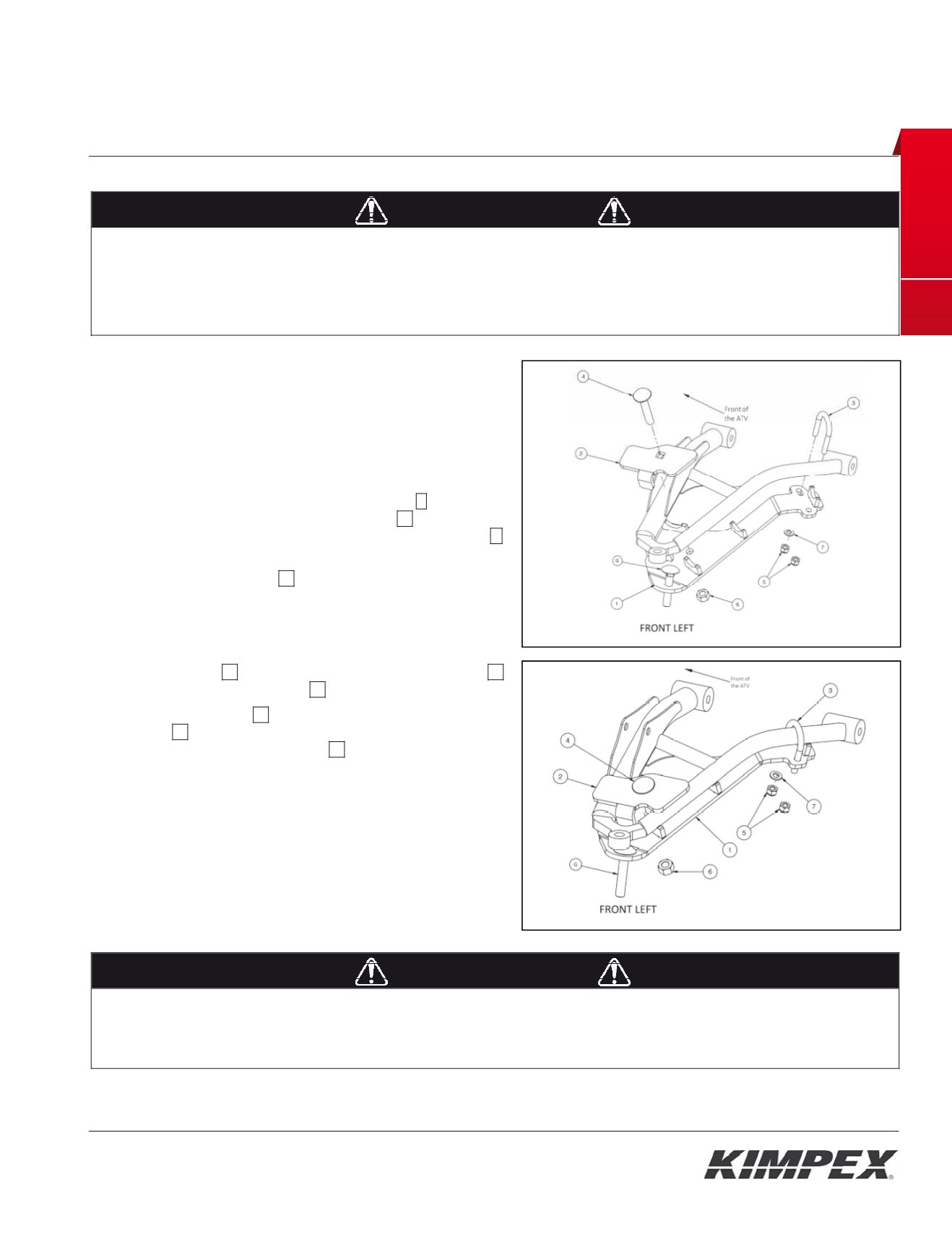
1) Remove the universal joint guard. Keep the parts for later
reinstallation.
2) Insert the M12-1.75 X 65-mm carriage screw
G
in the hole
identified by a label on the A-arm bracket
01
. See
figure 2.
In the packaging, this screw is mounted on the rod end
M
of the anti-rotation arm.
3) Lean the A-arm bracket
01
under the front lower
suspension arm taking care that the suspension table
tubes are firmly pressed down on the half-moon support
brackets of the A-arm bracket.
4) Fix the A-arm bracket to suspension arm using the front
clamping plate
02
, the M12-1.75 X 70-mm carriage bolt
04
and the M12-1.75 nylon nut
06
.
5) Place the M8 U-bolt
03
and fix it in place using an M8 flat
washer
07
(place the washer in the oblong hole side) and
the two (2) M8-1.25 nylon nuts
05
.
6) Ensure that the A-arm bracket is well positioned in the
half-moon support brackets and tighten all nuts in place.
WARNING
1.
Do not overtorque the bolts
. Some parts may be subject to deformations. If the bolts are too tight, safety aspects could be
compromised.
2.
Be careful: an incorrectly positioned A-arm bracket could give some play, which could make driving riskier as well as lead to breakage
to the vehicle, a loss of control and serious injuries.
Fig. 2
Fig. 3
I STA LATION M NUAL
FRONT AND REAR MOUNTING BRACKET KIT
KIMPEX N
°
375901
FOR CO MANDER TRACK YSTEM AND SPORTSMAN XP
I L
KIMPEX INC.
/ 5355, rue St-Roch / Drummondville (Québec) Canada / J2B 6V4
KIMPEX USA
/ 100 Walnut Street / Champlain (New York) / 12919
Lithographié au Canada / Litho’d in Canada
•
2810484
•
A-2810484-EN
4
Rear suspension brackets installation
WARNING
1.
The vehicle must be
immobilized
and the
engine turne ff
and cooled.
2.
lways wear
safety glasses
during installation, adjustment or repair.
3.
Please read and ensure you
have understood the warnings
an guidelines.
4.
ake sure the vehicle is
safely secured in place
by a system dedicated to this use (jack stands and hoist) and that it is supported or
fixed on locations that are not likely to br ak, bend or slip. A hydr ulic jack is not safe; nor is a log. T e vehicle must be not able to move.
The inst llation requires that the vehicle is in two-wheel drive mode with the gearbox in neutral. After lifting the vehicle
and removin the wheels:
1) Insert the rear suspension bracket
01
into the suspension table of the vehicle, by sliding it in the direction indicated
by th
figure 4A
by
arrows 1 and 2.
2) After making sure that the front support bracket is well positioned under the suspension table tube, fix the rear
suspension bracket
01
using the U-bolt
02
, the flat washer
04
(place the washer in the oblong hole side) and the two
(2) nylon nuts
03
. See
figure 4B
.
3) Tighten all bolts in place.
WARNING
1.
Do not overtorque the bolts
. Some parts may be subject to deformations. If the bolts are too tight, safety aspects could be compromised.
2.
Be careful: an incorrectly positioned Suspension bracket could give some play, which could make driving riskier as well as lead to
breakage to the vehicle, a loss of control and serious injuries.
A
Fig. 4
B


