2810180
KIMPEX INC.
/ 5355, rue St-Roch / Drummondville (Québec) Canada / J2B 6V4
KIMPEX USA
/ 100 Walnut Street / Champlain, New York / 12919
Lithographié au Canada / Litho’d in Canada
A-2810180 (F-00)
6/8
ATV
MOUNTING INSTRUCTIONS
FRONT AND REAR A-ARM BRACKET KIT
Kimpex
# 373216
FOR " COMMANDER " TRACK KIT / HONDA RUBICON
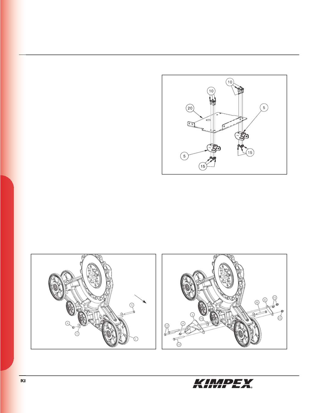
SNOWPLOW ADAPTER INSTALLATION
(see sketch E)
WARNING :
Prior to installation, turn off the engine, put
in two-wheel driving mode, and block the wheels.
WARNING :
When the ATV is raised, make sure that it is
properly secured/supported to prevent it from
accidentally falling during the installation. If not properly
secured/supported, serious physical injury could occur.
1)
Fasten the
(2)
rear anti-rotation arm supports (#
5
) onto the
snowplow adapter (#
20
) using
(6) 3/8” nc X 1”
hex bolts (#
10
) and
(6) 3/8” nc
self-locking nuts (#
15
).
NOTE :
Refer to the snowplow adapter mounting
instructions (no. 073216) to finish the installation.
REAR ANTI-ROTATION ARM BRACKET
INSTALLATION
(see sketch F)
1)
Unscrew the self-locking nut (#
A
) from the 1/2” nc X 6” hex bolt (#
B
) retaining the wheel closer to the adjustment slide (#
C
). Remove
and discard the flat washer (#
D
).
(see sketch G)
2)
Assemble the rear right anti-rotation arm bracket (#
6
) to the hole made for this purpose in the plastic frame of the Track Kit using
(3) 3/8” nc X 3-1/2”
hex bolts (#
12
), a
3/8” I.D. X 1-1/4” O.D. X .120”
Fender washer (#
19
), the rear anti-rotation arm clamping plate (#
8
),
(3) 3/8”
nc self-locking nuts (#
15
), and the original self-locking nut (#
A
) removed in
step 1
.
3)
Repeat
steps 1
and
2
for the opposite side.
sketch E
sketch F
RIGHT
REAR VIEW
Rear of
the ATV
sketch G


