KIMPEX INC.
/ 5355, rue St-Roch / Drummondville (Québec) Canada / J2B 6V4
KIMPEX USA
/ 100 Walnut Street / Champlain, New York / 12919
Lithographié au Canada / Litho’d in Canada
A-2810258
2810258
9/9
ATV
MOUNTING INSTRUCTIONS
FRONT AND REAR A-ARM BRACKET KIT
Kimpex
# 375411
For "Commander Wide Track" and "Commander Trek" track kit
Polaris Sportsman 1997-2004
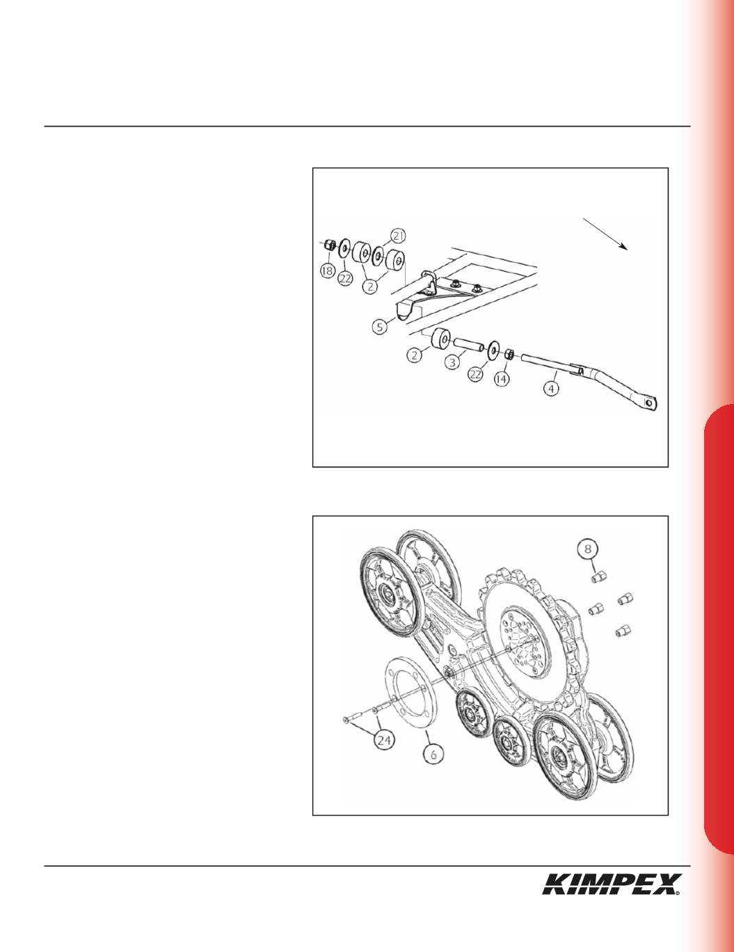
REAR ANTI-ROTATION INSTALLATION
(see sketch J)
1)
Screw the
5/8” nc
nut (#
14
) onto the threaded part
of the anti-rotation tube (#
4
).
2)
Install the
17mm I.D. X 50mm O.D. X 3mm
flat washer
(#
22
) and the bushing spacer tube (#
3
) onto the
threaded part of the anti-rotation tube (#
4
).
3)
Install the rubber bushing (#
2
) over the bushing
spacer tube (#
3
).
4)
Slide the anti-rotation assembly into the hole on the
bottom of the rear A-arm bracket (#
5
).
5)
Install the rubber bushing (#
2
), the
3/4” I.D. X 2” O.D.
X 1/8”
flat washer (#
21
), and the other rubber
bushing (#
2
) over the bushing spacer tube (#
3
).
6)
Install the
17mm I.D. X 50mm O.D. X 3mm
flat washer
(#
22
) onto the threaded part of the anti-rotation
tube (#
4
).
7)
Screw the
5/8” nc
self-locking nut (#
18
) onto the
threaded part of the anti-rotation tube (#
4
).
Do not overtighten.
NOTE :
Refer to the Track Kit manual for the
correct adjustment.
8)
Repeat
steps 1
to
7
for the opposite side.
9)
Reinstall the rear CV shield removed during
step 2
of
the
“REAR
A-ARM
BRACKET
INSTALLATION” section
using the original
hardware.
MAIN AXLE ADAPTER INSTALLATION
(see sketch K)
1)
Remove and discard only one bolt retaining the
sprocket to the main axle of the Track Kit.
NOTE :
Pay special attention to the
orientation given to the main axle adapter
(#6) during installation. The lip, of the main
axle adapter, must fit perfectly the circumfer-
ence of the main axle.
2)
Position the main axle adapter (#
6
) and fasten
using the
(2) 3/8” nc X 2-1/4”
Allen socket machine
screws (#
24
). Torque to 20 ft-lbs.
3)
Install the Track Kit onto the hub of the ATV using
the
(4) 3/8” nc
“T” nuts (#
8
). Torque to 25 ft-lbs.
NOTE :
Recheck torque of the “T” nuts (#8)
after one hour of use.
4)
Repeat
steps 1
to
3
for the opposite side.
sketch J
LEFT
REAR VIEW
sketch K
Rear of the ATV


