2810247
KIMPEX INC.
/ 5355, rue St-Roch / Drummondville (Québec) Canada / J2B 6V4
KIMPEX USA
/ 100 Walnut Street / Champlain, New York / 12919
Lithographié au Canada / Litho’d in Canada
A-2810247
9/9
ATV
MOUNTING INSTRUCTIONS
FRONT AND REAR A-ARM BRACKET KIT
Kimpex
# 374430
FOR " COMMANDER WIDE TRACK " AND " COMMANDER TREK HD " TRACK KIT / POLARIS RANGER RZR
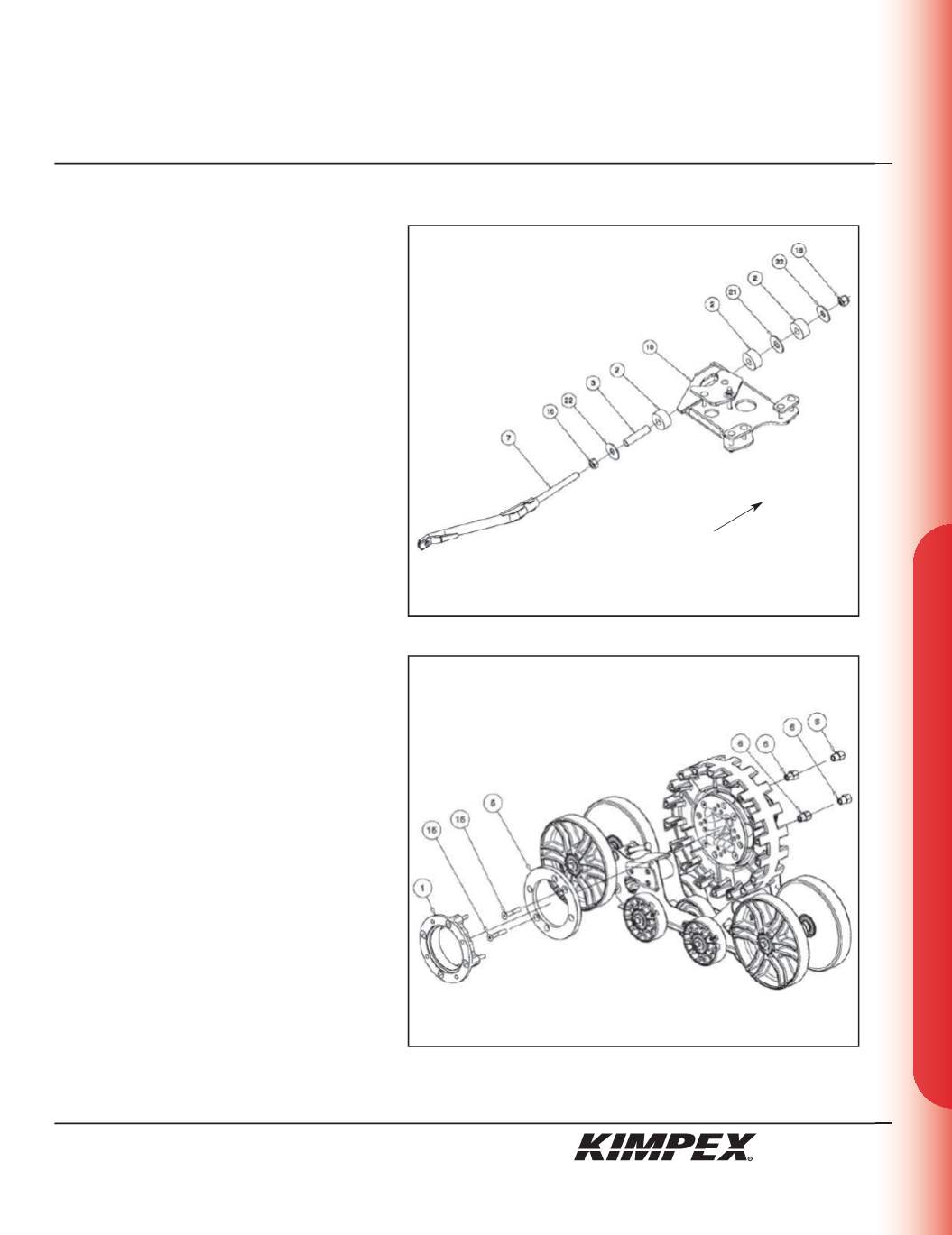
REAR ANTI-ROTATION INSTALLATION
(see sketch I)
1)
Screw the
5/8” nc
nut (#
16
) onto the threaded part
of the anti-rotation tube (#
7
).
2)
Install the
17mm I.D. X 50mm O.D. X 3mm
flat washer
(#
22
) and the bushing spacer tube (#
3
) onto the
threaded part of the anti-rotation tube (#
7
).
3)
Install the rubber bushing (#
2
) over the bushing
spacer tube (#
3
).
4)
Slide the anti-rotation assembly into the hole on
the bottom of the rear A-arm bracket (#
10
).
5)
Install the rubber bushing (#
2
), the
3/4” I.D. X 2” O.D.
X 1/8”
flat washer (#
21
), and the other rubber
bushing (#
2
) over the bushing spacer tube (#
3
).
6)
Install the
17mm I.D. X 50mm O.D. X 3mm
flat washer
(#
22
) onto the threaded part of the anti-rotation
tube (#
7
).
7)
Screw the
5/8” nc
self-locking nut (#
18
) onto the
threaded part of the anti-rotation tube (#
7
).
Do not overtighten.
NOTE :
Refer to the Track Kit manual for the
correct adjustment.
8)
Repeat
steps 1
to
7
for the opposite side.
MAIN AXLE ADAPTER INSTALLATION
(see sketch J)
1)
Remove and discard two bolts retaining the
sprocket to the main axle of the Track Kit.
NOTE :
Pay special attention to the
orientation given to the main axle adapter
(#5) during installation. The lip, of the main
axle adapter, must fit perfectly the circumfer-
ence of the main axle.
2)
Position the spacer (#
1
) onto the hub and secure
with the existing nuts.
3)
Position the main axle adapter (#
5
) and fasten
using the
(2) 3/8” nc X 2-1/4”
Allen socket machine
screws (#
15
). Torque to 20 ft-lbs.
4)
Install the Track Kit onto the hub of the ATV using
the
(4) 3/8” nf
“T” nuts (#
6
). Torque to 25 ft-lbs.
NOTE :
Recheck torque of the “T” nuts (#6)
after one hour of use.
5)
Repeat
steps 1
to
4
for the opposite side.
sketch I
LEFT
REAR VIEW
sketch J
Front of the ATV


