8/10
ATV
KIMPEX INC.
/ 5355, rue St-Roch / Drummondville (Québec) Canada / J2B 6V4
KIMPEX USA
/ 100 Walnut Street / Champlain, New York / 12919
Lithographié au Canada / Litho’d in Canada
2810341
A-2810341 Rev. C
FRONT AND REAR A-ARM BRACKET KIT
Kimpex
#
375413
For Commander Wide Track, WTX, and TREX 2.0 Track Kits
MOUNTING INSTRUCTIONS
8
sketch I
LEFT
REAR VIEW
Rear of the ATV
LEFT REAR VIEW
Rear of
the ATV
Rear of
the ATV
sketch J
2005-2007 Models
2008 - 2010 Models
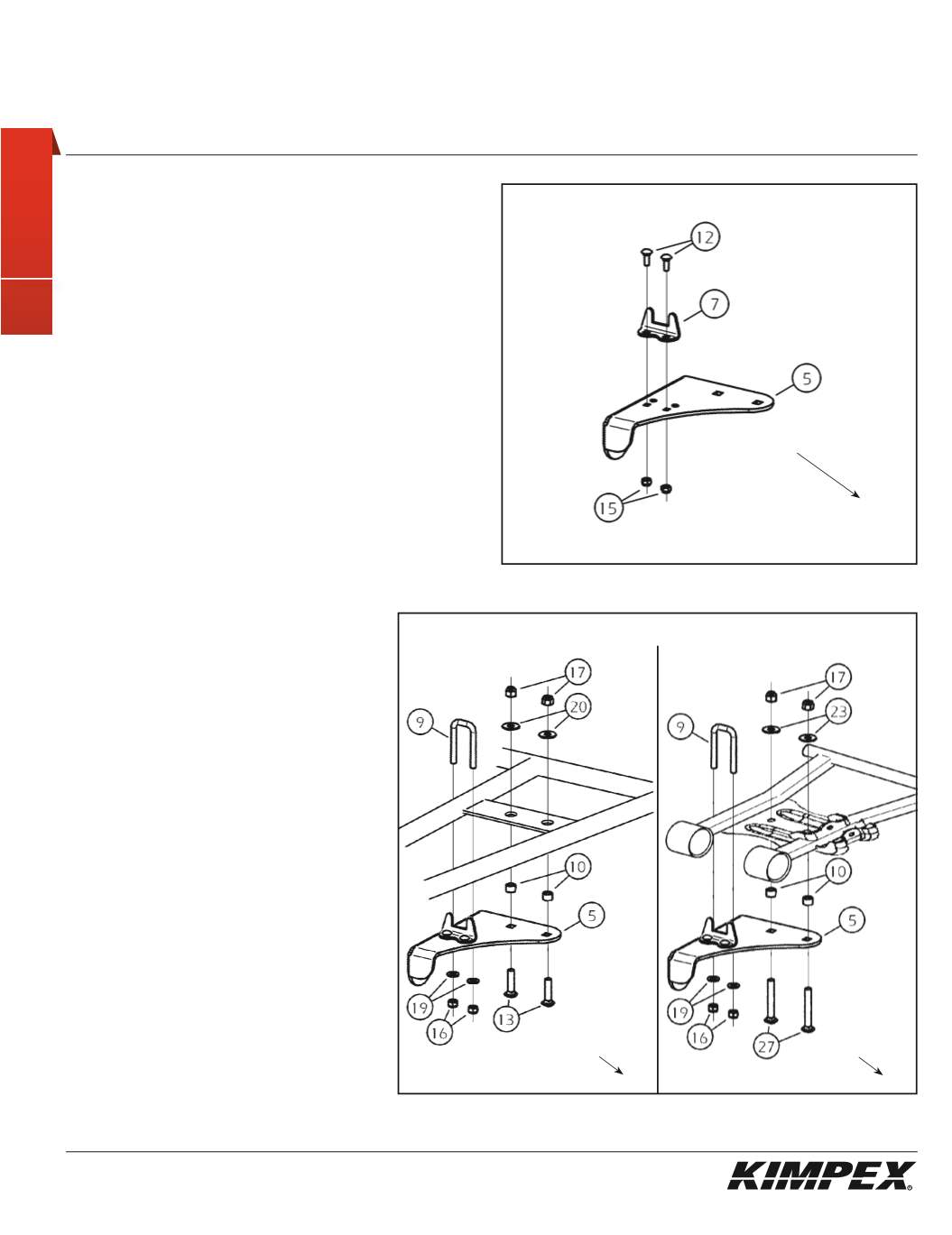
REAR A-ARM BRACKET INSTALLATION
(see sketch I)
WARNING:
Prior to installation, turn off the engine, put
in two-wheel driving mode and the transmission in
neutral, and block the wheels.
1)
Raise the rear of the ATV off the ground and remove the wheels.
WARNING:
When the ATV is raised, make sure that it is
properly secured/supported to prevent it fromaccidentally
falling during the installation of the sub-tables. If not
properly secured/supported, serious physical injury could
occur.
2)
Remove the rear left CV shield. Do not discard. They will be
reinstalled later.
3)
Assemble the rear A-arm bracket guide (#
7
) onto the rear left
A-arm bracket (#
5
) using the
(2) 1/4” nc X 3/4”
carriage bolts (#
12
)
and the
(2) 1/4” nc
self-locking nuts (#
15
). Torque to 7 ft-lbs.
(see sketch J)
4)
Install the
(2) 3/8” nc X 1-1/2”
carriage bolts (#
13
- 2005-2007 Models
) or the
(2) 3/8” nc X 2-3/4”
carriage bolts (#
27 - 2008 - 2010 Models
).
Slide the
(2) 9/16” O.D. X .397” I.D. X 3/8”
spacers
(#
10
) onto the bolts (#
13
or #
27
) (one spacer
on each bolt).
5)
Place the rear A-arm bracket (#
5
) below the
rear lower a-arm. Install the
(2) 3/8” dia
flat
washers (#
20 - 2005-2007 Models
) or the
(2)
3/8” I.D. X 1-1/4” O.D. X .120”
Fender washers (#
23
- 2008 - 2010 Models
) and the
(2) 3/8” nc
self-
locking nuts (#
17
) on the top of the rear lower
a-arm (screw the first threads only).
6)
Install the
5/16” nc X 2-3/4”
U-bolt (#
9
) over the
rear lower a-arm into the intended mounting
holes of the rear A-arm bracket (#
5
). Install the
(2) 5/16” dia
flat washers (#
19
) and the
(2) 5/16” nc
self-locking nuts (#
16
).
7)
Tighten all the bolts. Torque the
5/16” nc
bolts
(#
16
) to 15 ft-lbs and the
3/8” nc
bolts (#
13
or
#
27
) to 25 ft-lbs.


