2810243


            KIMPEX INC.


          / 5355, rue St-Roch / Drummondville (Québec) Canada / J2B 6V4


            KIMPEX USA


          / 100 Walnut Street / Champlain, New York / 12919
        
        
          Lithographié au Canada / Litho’d in Canada
        
        
          )
        
        
          NT BUMPER
        
        
          Kimpex
        
        
          #
        
        
          072915
        
        
          aha Wolverine 1995


            MOUNTING INSTRUCTIONS


          ription
        
        
          Item No.
        
        
          Quantity
        
        
          t bumper
        
        
          81-828-1000
        
        
          1
        
        
          ort
        
        
          81-828-2000
        
        
          2
        
        
          ” nc X 3/4” hex  bolt
        
        
          S1711-00506-022 2
        
        
          ” nc X 2” hex bolt
        
        
          S1711-00516-022 4
        
        
          Ref. Description
        
        
          Item No.
        
        
          Quantity
        
        
          �
        
        
          5/16” nc self-locking nut
        
        
          S4186-10500-022 6
        
        
          �
        
        
          1” dia X 4-1/4” “U” bracket
        
        
          Q2116-20002
        
        
          2
        
        
          �
        
        
          1” dia X 4-5/8” “U” bracket
        
        
          Q2118-20001
        
        
          2
        
        
          �
        
        
          Plastic cap
        
        
          S8111-00007-500 2
        
        
          o install a winch on a Kimpex front bumper, use the rear position holes, if not use the front holes.
        
        
          the front bumper
        
        
          �
        
        
          under the lower tube of the wire netting.
        
        
          (See sketch A)
        
        
          er tube of the wire netting, fasten using
        
        
          1-1/8” dia X 4-5/8”
        
        
          “U” brackets
        
        
          �
        
        
          ,
        
        
          5/16” nc X 2”
        
        
          hex bolts
        
        
          �
        
        
          , and
        
        
          c
        
        
          self-locking nuts
        
        
          �
        
        
          .
        
        
          the lower part of the front bumper using the two supports
        
        
          �
        
        
          ,
        
        
          1” dia X 4-1/4”
        
        
          “U” brackets
        
        
          �
        
        
          ,
        
        
          c X 2”
        
        
          hex bolts
        
        
          �
        
        
          , and
        
        
          5/16” nc
        
        
          self-locking nuts
        
        
          �
        
        
          , on to the original frame.
        
        
          (See sketch B)
        
        
          the supports
        
        
          �
        
        
          under the bumper
        
        
          �
        
        
          using
        
        
          5/16” nc X 3/4”
        
        
          hex bolts
        
        
          �
        
        
          and
        
        
          5/16” nc
        
        
          self-locking nuts
        
        
          �
        
        
          .
        
        
          in place.
        
        
          (See sketch C)
        
        
          the plastic caps
        
        
          �
        
        
          to the two ends of the tube.
        
        
          (See sketch D)
        
        
          C
        
        
          sketch D
        
        
          A
        
        
          sketch B
        
        
          A-2810243
        
        
          ATV


            Mounting instructions


          front and REAR A-ARM BRACKET KIT
        
        
          Kimpex


            # 375717


          For " Commander wide track " and " commander trek " track kits / yamaha grizzly 600, big bear 350


            KIMPEX INC.


          / 5355, rue St-Roch / Drummondville (Québec) Canada / J2B 6V4


            KIMPEX USA


          / 100 Walnut Street / Champlain, New York / 12919
        
        
          Lithographié au Canada / Litho’d in Canada
        
        
          2810243
        
        
          A-2810243
        
        
          FRONT AND REAR A-ARM BRACKET KIT
        
        
          Kimpex
        
        
          #
        
        
          375717
        
        
          For “Commander Wide Track” and “Commander Trek” Track Kit


            MOUNTING INSTRUCTIONS


          7


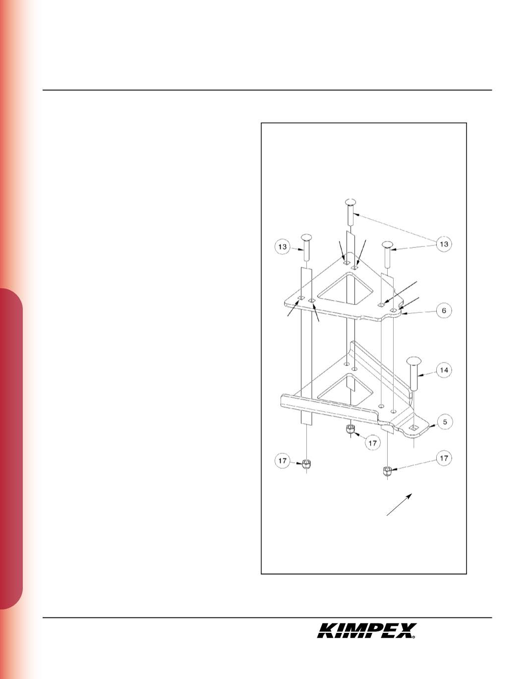
            FRONT A-ARM BRACKET INSTALLATION


            (see sketch D)


            WARNING :


          Prior to installation, turn off the engine, put
        
        
          in two-wheel driving mode, and block the wheels.
        
        
          1)
        
        
          Raise the front of the ATV off the ground and remove the
        
        
          wheels.


            WARNING :


          When the ATV is raised, make sure that it is
        
        
          properly secured/supported to prevent it from
        
        
          accid ntally falling during the installat on of the sub-
        
        
          tables. If not properly secured/supported, serious
        
        
          physical injury could occur.
        
        
          2)
        
        
          Remove the front right CV shield. Do not discard. They will be
        
        
          reinstalled later.
        
        
          3)
        
        
          Insert the
        
        
          1/2” nc X 2-1/2”
        
        
          carriage bolt (#
        
        
          4
        
        
          ) into the ole
        
        
          intended in the front right A-arm bracket (#
        
        
          5
        
        
          ).
        
        
          4)
        
        
          Install the front right A-arm bracket (#
        
        
          5
        
        
          ) under the lower front a-
        
        
          arm so that the two parts fit snugly.


            IMPORTANT :


          Make sure to use the correct mounting
        
        
          holes.
        
        
          5)
        
        
          Install the front A-arm clamping plate (#
        
        
          6
        
        
          ) above the lower front
        
        
          a-arm and fasten them to the A-arm bracket (#
        
        
          5
        
        
          ) using the
        
        
          (3)
        
        
          3/8” nc X 2”
        
        
          carriage bolts (#
        
        
          13
        
        
          ) and the
        
        
          (3) 3/8” nc
        
        
          self-locking nuts
        
        
          (#
        
        
          17
        
        
          ).
        
        
          Torque to 20 ft-lbs


            IMPORTANT :


          Tighten in a manner not to permanently
        
        
          deform the assembly.
        
        
          6)
        
        
          Repeat
        
        
          steps 2
        
        
          to
        
        
          5
        
        
          for the opposite side.
        
        
          sketch D
        
        
          RIGHT
        
        
          FRONT VIEW
        
        
          Front of the ATV
        
        
          Big Bear
        
        
          350
        
        
          Big Bear
        
        
          350
        
        
          Big Bear
        
        
          350
        
        
          Grizzly
        
        
          600
        
        
          Grizzly
        
        
          600
        
        
          Grizzly
        
        
          600