2810349
KIMPEX INC.
/ 5355, rue St-Roch / Drummondville (Québec) Canada / J2B 6V4
KIMPEX USA
/ 100 Walnut Street / Champlain, New York / 12919
Lithographié au Canada / Litho’d in Canada
)
NT BUMPER
Kimpex
#
072915
aha Wolverine 1995
MOUNTING INSTRUCTIONS
ription
Item No.
Quantity
bumper
81-828-1000
1
ort
81-828-2000
2
” nc X 3/4” hex bolt
S1711-00506-022 2
” nc X 2” hex bolt
S1711-00516-022 4
Ref. Description
Item No.
Quantity
�
5/16” nc self-locking nut
S4186-10500-022 6
�
1” dia X 4-1/4” “U” bracket
Q2116-20002
2
�
1” dia X 4-5/8” “U” bracket
Q2118-20001
2
�
Plastic cap
S8111-00007-500 2
install a winch on a Kimpex front bumper, use the rear position holes, if not use the front holes.
the front bumper
�
under the lower tube of the wire netting.
(See sketch A)
er tube of the wire netting, fasten using
1-1/8” dia X 4-5/8”
“U” brackets
�
,
5/16” nc X 2”
hex bolts
�
, and
c
self-locking nuts
�
.
the lower part of the front bumper using the two supports
�
,
1” dia X 4-1/4”
“U” brackets
�
,
c X 2”
hex bolts
�
, and
5/16” nc
self-locking nuts
�
, on to the original frame.
(See sketch B)
the supports
�
under the bumper
�
using
5/16” nc X 3/4”
hex bolts
�
and
5/16” nc
self-locking nuts
�
.
in place.
(See sketch C)
the plastic caps
�
to the two ends of the tube.
(See sketch D)
sketch D
sketch B
A-2810349
ATV
Mounting instructions
front and REAR A-ARM BRACKET KIT
Kimpex
# 375716
For " Commander wide track " and " commander trek " track kits / yamaha kodiak 400, 450 (rear swingarm susp.)
KIMPEX INC.
/ 5355, rue St-Roch / Drummondville (Québec) Canada / J2B 6V4
KIMPEX USA
/ 100 Walnut Street / Champlain, New York / 12919
Lithographié au Canada / Litho’d in Canada
2810349
A-2810349
FRONT AND REAR A-ARM BRACKET KIT
Kimpex
#
375716
For “Commander Wide Track” and “Commander Trek” Track Kit
MOUNTING INSTRUCTIONS
12
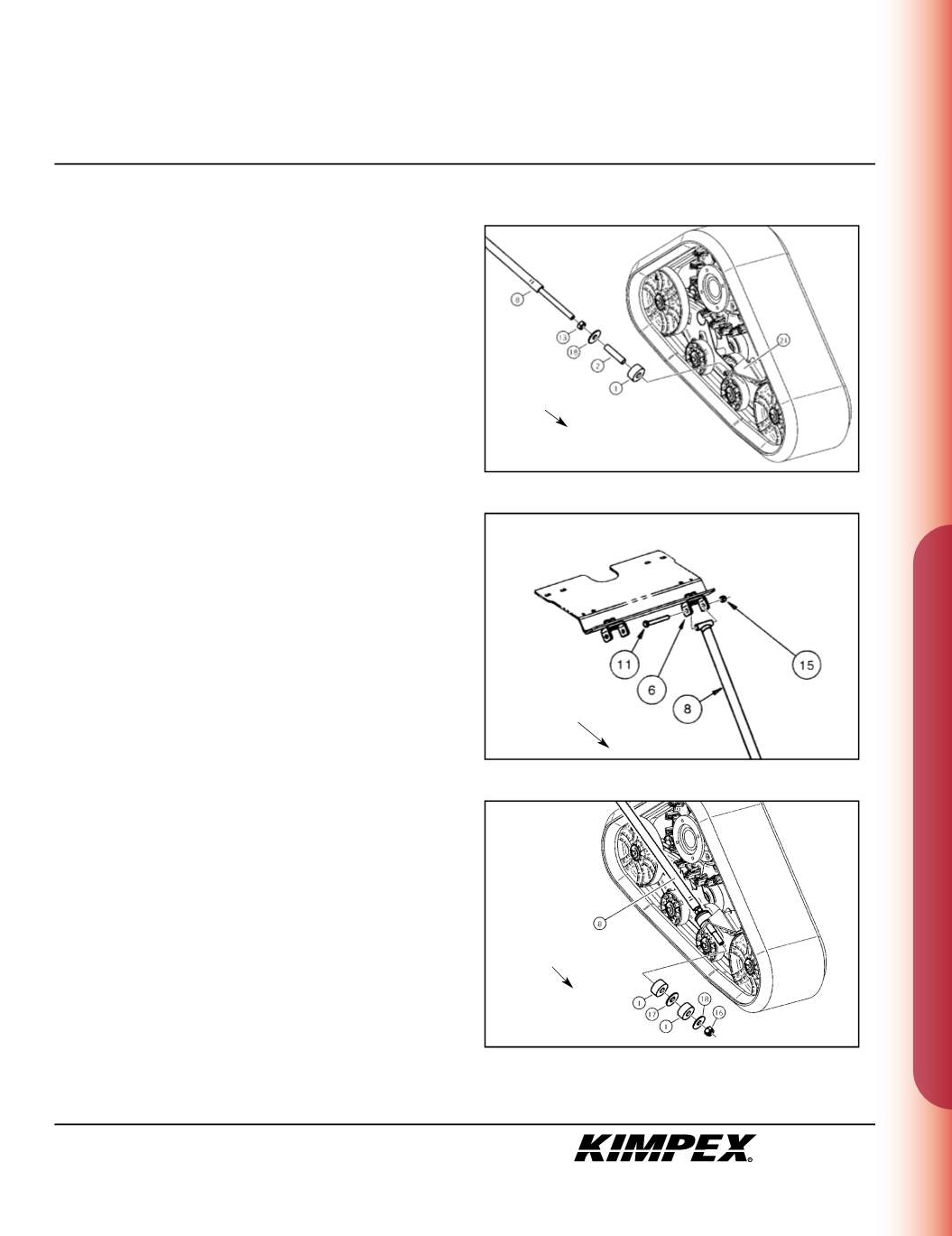
“COMMANDER TREK”
REAR ANTI-ROTATION INSTALLATION
(see sketch Q)
1)
Screw the
5/8” nc
nut (#
13
) onto the threaded part of the anti-
rotation arm (#
8
).
2)
Install the
17mm I.D. X 50mm O.D. X 3mm
flat washer (#
18
) and the
bushing spacer tube (#
2
) onto the threaded part of the anti-
rotation arm (#
8
).
3)
Install the rubber bushing (#
1
) over the bushing spacer tube
(#
2
).
4)
Slide the anti-rotation arm assembly into the hole of the rear
ight an i-rotation arm bracket (#
21
).
(see sketch R)
5)
Fasten the other end of the rear anti-rotation arm (#
8
) onto the
rear anti-rotation arm support (#
6
) installed in
step 2 at the
“SNOWPLOW ADAPTER INSTALLATION” s ction
using the
3/8” nc X 3”
hex bolt (#
11
) and the
3/8” nc
self-locking nut (#
15
).
(see sketch S)
6)
Install the rubber bushing (#
1
), the
3/4” I.D. X 2” O.D. X 1/8”
flat
washer (#
17
), and the other rubber bushing (#
1
) over the
bushing spacer tube (#
2
).
7)
Install the
17mm I.D. X 50mm O.D. X 3mm
flat washer (#
18
) onto the
threaded part of the anti-rotation arm (#
8
).
8)
Screw the
5/8” nc
self-locking nut (#
16
) onto the threaded part of
the anti-rotation arm (#
8
). Do not overtighten.
NOTE :
Refer to the Track Kit manual to complete the
installation.
9)
Repeat
steps 1
to
8
for the opposite side.
Rear of
the ATV
sketch Q
sketch R
sketch S
RIGHT
REAR VIEW
RIGHT
REAR VIEW
Rear of
the ATV
Rear of
the ATV


