2810150
KIMPEX INC.
/ 5355, rue St-Roch / Drummondville (Québec) Canada / J2B 6V4
KIMPEX USA
/ 100 Walnut Street / Champlain, New York / 12919
Lithographié au Canada / Litho’d in Canada
A-2810150 (F-00))
5/6
ATV
MOUNTING INSTRUCTIONS
FRONT AND REAR A-ARM BRACKET KIT
Kimpex
# 373310
FOR " COMMANDER " TRACK KIT / KAWASAKI BRUTE FORCE 750
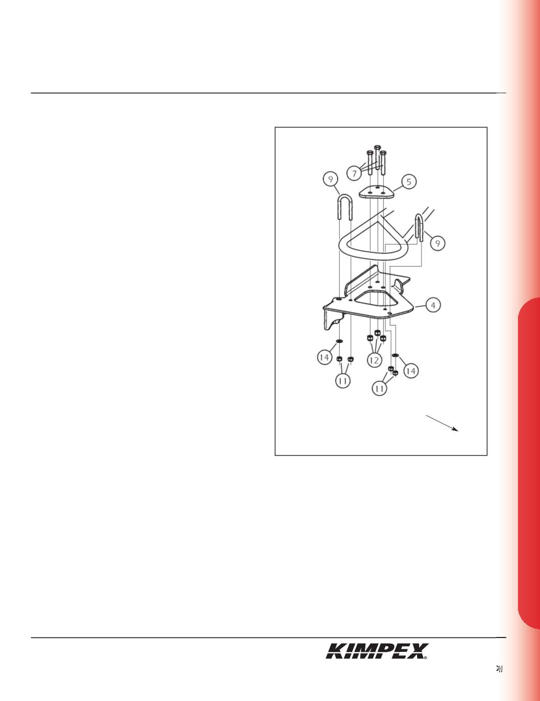
REAR A-ARM BRACKET INSTALLATION
(see sketch C)
WARNING :
Prior to installation, turn off the engine, put
in two-wheel driving mode, and block the wheels.
1)
Raise the rear of the ATV off the ground and remove the wheels.
WARNING :
When the ATV is raised, make sure that it is
properly secured/supported to prevent it from
accidentally falling during the installation of the sub-
tables. If not properly secured/supported, serious
physical injury could occur.
2)
Remove the rear left CV shield. Do not discard. They will be
reinstalled later.
3)
Place the rear A-arm bracket (#
4
) below the rear lower A-arm so
that the two parts fit snugly.
4)
Install the
(2) 5/16” nc X 2.188”
U-bolts (#
9
) over the rear lower
A-arm into the intended mounting holes of the rear A-arm
bracket (#
4
). Install the
(2) 5/16” dia
flat washers (#
14
) and the
(4)
5/16” nc
self-locking nuts (#
11
) (screw the first threads only).
5)
Install the tightening plate (#
5
) over the rear lower A-arm and
fasten it to the A-arm bracket (#
4
) using the
(3) 3/8” nc X 2-1/2”
hex
bolts (#
7
) and the
(3) 3/8” nc
self-locking nuts (#
12
).
6)
Tighten all the bolts. Torque the
5/16” nc
nuts (#
11
) to 15 ft-lbs
and the
3/8” nc
nuts (#
12
) to 20 ft-lbs.
IMPORTANT :
Tighten in a manner not to permanently
deform the assembly.
sketch C
LEFT
REAR VIEW
Rear of the ATV


