8/10
ATV
INSTALLATIONMANUAL
FRONTANDREARMOUNTINGBRACKETKIT
KIMPEXN
o
374365
FORCOMMANDERTRACKSYSTEMANDKAWASAKI TERYX4VEHICLE
KIMPEX INC.
/ 5355, rue St-Roch /Drummondville (Québec) Canada / J2B6V4
KIMPEXUSA
/ 100Walnut Street /Champlain (NewYork) / 12919
LithographiéauCanada / Litho’d inCanada
•
2810461
•
A-2810461-EN-rev.a
8
Installationof the frontA-armbrackets
WARNING
1.
Thevehiclemust be
immobilized
and the
engine turnedoff
andcooled.
2.
Alwayswear
safetyglasses
during installation, adjustment or repair.
3.
Please readandensure you
haveunderstood thewarnings
andguidelines.
4.
Make sure the vehicle is
safelysecured inplace
bya systemdedicated to this use (jack stands andhoist) and that it is supportedor
fixedon locations that arenot likely tobreak, bendor slip. Ahydraulic jack is not safe; nor is a log. The vehiclemust benot able tomove.
The installation requires that the vehicle is in two-wheel drivemodewith thegearbox inneutral. After lifting the vehicle
and removing thewheels:
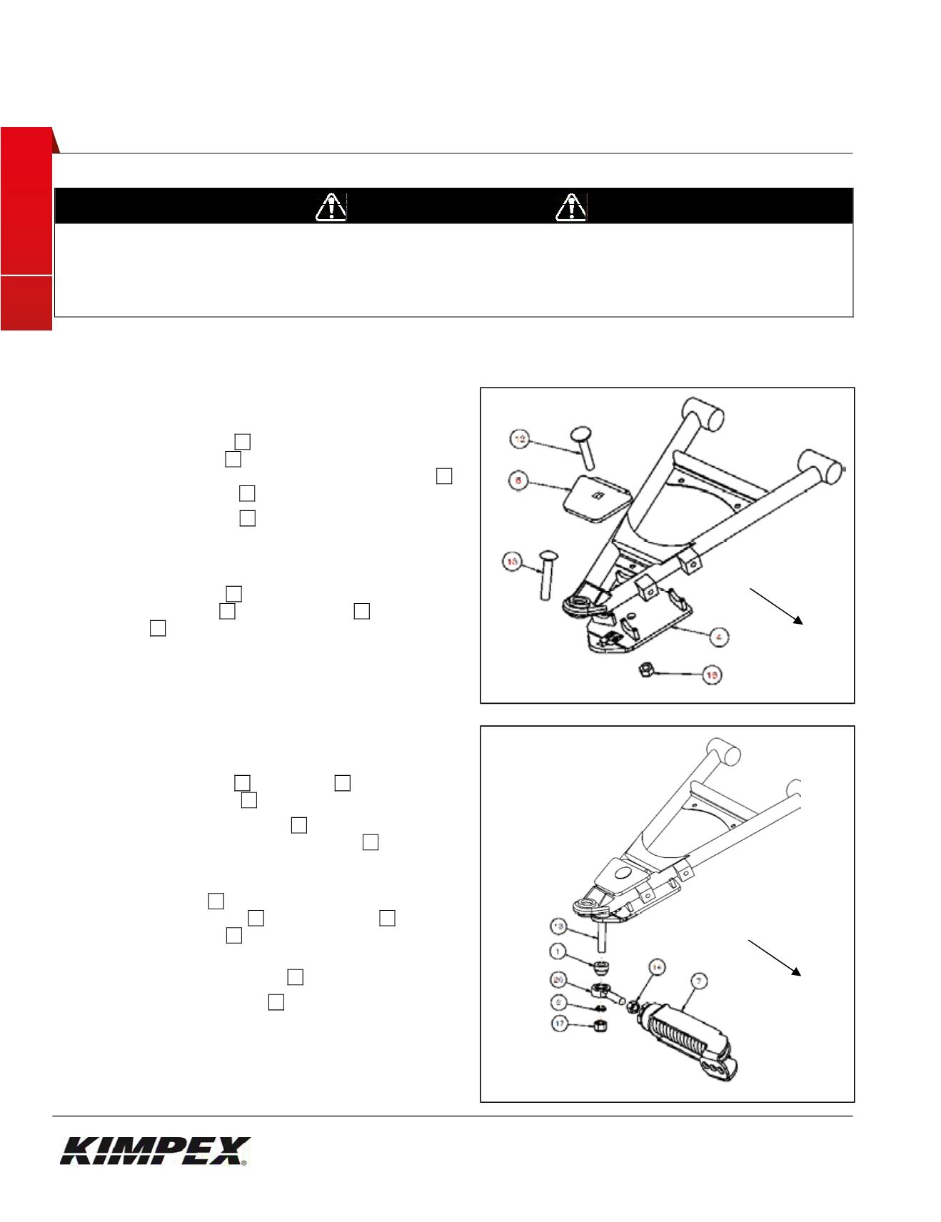
1) Remove theuniversal joint guard. Keepparts for later
reinstallation.
2) Insert the carriagebolt
13
in thehole identifiedbya label
on theA-armbracket
04
. See
figure7.
In thepackaging, this bolt ismountedon the rodend
20
of theanti-rotationarm
07
. See
figure8
3) Lean theA-armbracket
04
under the front lower
suspensionarm taking care that the suspension table
tubes are firmlypresseddownon thehalf-moonbrackets
of theA-armbracket. See
figure7.
4) Fix theA-armbracket
04
to the suspensionarmusing
front clampingplate
05
, the carriagebolt
12
and the
nylonnut
18
.
5) Ensure that theA-armbracket iswell positioned in the
half-moonbrackets and tightenall nuts inplace.
Installationof the front anti-rotationarm
1) Assemble theball joint
20
and thenut
14
to theanti-
rotationarmassembled
07
. See
figure8.
2) Insert the largeball joint spacer
01
(with the taperedpart
pointingdownwards) on the carriagebolt
13
(Inserted in
step2of the section "Installationof the frontA-arm
brackets").
Figure8
3) Insert theball joint
20
of theanti-rotationarmassembled
after theball joint spacer
01
into thehexbolt
13
. Insert the
short ball joint spacer
02
belowwith the tapered sideup.
Figure8
4) Tightenall using thenylonnut
17
. Torque to65 ft-lbs.
5) Rotate theanti-rotationarm
07
inwardlyof the vehicle to
prevent it interferewith the installationof the track kit
system.
6) Repeat
steps1
to
5
for theopposite side.
Fig. 7
Front of theUTV
Fig. 8
Front of theUTV


