2810266


            KIMPEX INC.


          / 5355, rue St-Roch / Drummondville (Québec) Canada / J2B 6V4


            KIMPEX USA


          / 100 Walnut Street / Champlain, New York / 12919
        
        
          Lithographié au Canada / Litho’d in Canada
        
        
          )
        
        
          NT BUMPER
        
        
          Kimpex
        
        
          #
        
        
          072915
        
        
          aha Wolverine 1995


            MOUNTING INSTRUCTIONS


          ription
        
        
          Item No.
        
        
          Quantity
        
        
          bumper
        
        
          81-828-1000
        
        
          1
        
        
          ort
        
        
          81-828-2000
        
        
          2
        
        
          ” nc X 3/4” hex  bolt
        
        
          S1711-00506-022 2
        
        
          ” nc X 2” hex bolt
        
        
          S1711-00516-022 4
        
        
          Ref. Description
        
        
          Item No.
        
        
          Quantity
        
        
          �
        
        
          5/16” nc self-locking nut
        
        
          S4186-10500-022 6
        
        
          �
        
        
          1” dia X 4-1/4” “U” bracket
        
        
          Q2116-20002
        
        
          2
        
        
          �
        
        
          1” dia X 4-5/8” “U” bracket
        
        
          Q2118-20001
        
        
          2
        
        
          �
        
        
          Plastic cap
        
        
          S8111-00007-500 2
        
        
          install a winch on a Kimpex front bumper, use the rear position holes, if not use the front holes.
        
        
          the front bumper
        
        
          �
        
        
          under the lower tube of the wire netting.
        
        
          (See sketch A)
        
        
          er tube of the wire netting, fasten using
        
        
          1-1/8” dia X 4-5/8”
        
        
          “U” brackets
        
        
          �
        
        
          ,
        
        
          5/16” nc X 2”
        
        
          hex bolts
        
        
          �
        
        
          , and
        
        
          c
        
        
          self-locking nuts
        
        
          �
        
        
          .
        
        
          the lower part of the front bumper using the two supports
        
        
          �
        
        
          ,
        
        
          1” dia X 4-1/4”
        
        
          “U” brackets
        
        
          �
        
        
          ,
        
        
          c X 2”
        
        
          hex bolts
        
        
          �
        
        
          , and
        
        
          5/16” nc
        
        
          self-locking nuts
        
        
          �
        
        
          , on to the original frame.
        
        
          (See sketch B)
        
        
          the supports
        
        
          �
        
        
          under the bumper
        
        
          �
        
        
          using
        
        
          5/16” nc X 3/4”
        
        
          hex bolts
        
        
          �
        
        
          and
        
        
          5/16” nc
        
        
          self-locking nuts
        
        
          �
        
        
          .
        
        
          in place.
        
        
          (See sketch C)
        
        
          the plastic caps
        
        
          �
        
        
          to the two ends of the tube.
        
        
          (See sketch D)
        
        
          sketch D
        
        
          sketch B
        
        
          A-2810266 Rév. A
        
        
          ATV


            Mounting instructions


          front and REAR A-ARM BRACKET KIT
        
        
          Kimpex


            # 375715


          For " Commander wide track " and " commander trek " track kits / yamaha kodiak 400, 450 (rear swingarm susp.)


            KIMPEX INC.


          / 5355, rue St-Roch / Drummondville (Québec) Canada / J2B 6V4


            KIMPEX USA


          / 100 Walnut Street / Champlain, New York / 12919
        
        
          Lithographié au Canada / Litho’d in Canada
        
        
          2810266
        
        
          A-2810266  Rév. A
        
        
          FRONT AND REAR A-ARM BRACKET KIT
        
        
          Kimpex
        
        
          #
        
        
          375715
        
        
          For “Commander Wide Track” and “Commander Trek” Track Kit


            MOUNTING INSTRUCTIONS


          8


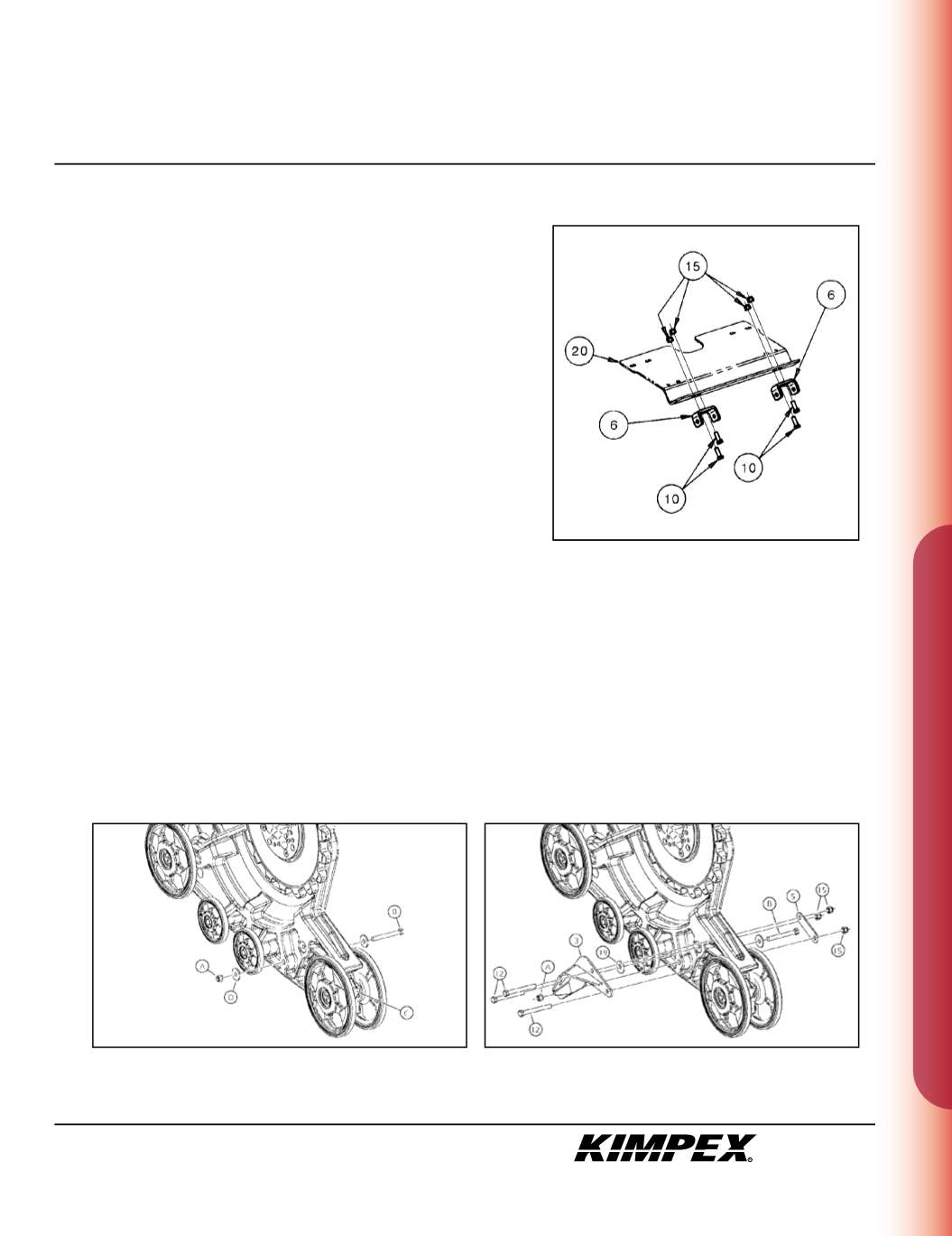
            SNOWPLOW ADAPTER INSTALLATION


            (see sketch F)


            WARNING :


          Prior to installation, turn off the engine, put in two-
        
        
          wheel driving mode, and block the wheels.


            WARNING :


          When the ATV is raised, make sure that it is properly
        
        
          secured/supported to prevent it from accidentally falling during the
        
        
          installation. If not properly secured/supported, serious physical
        
        
          injury could occur.
        
        
          1)
        
        
          Fasten the
        
        
          (2)
        
        
          rear anti-rotation arm supports (#
        
        
          6
        
        
          ) onto the snowplow
        
        
          adapter (#
        
        
          20
        
        
          ) using the
        
        
          (4) 3/8” nc X 1”
        
        
          hex bolts (#
        
        
          10
        
        
          ) and the
        
        
          (4) 3/8” nc
        
        
          self-
        
        
          locking nuts (#
        
        
          15
        
        
          ).


            NOTE :


          Refer to the snowplow adapter m unting instructions
        
        
          (no. 073752) to finish the installation.


            • TO FINISH THE INSTALLATION OF “COMMANDER WIDE TRACK”


            MODELS, SEE PAGES 8 TO 10.


            • TO FINISH THE INSTALLATION OF “COMMANDER TREK”


            MODELS, SEE PAGES 11 AND 12.


            “COMMANDER WIDE TRACK” / REAR ANTI-ROTATION ARM BRACKET INSTALLATION


            (see sketch G)


          1)
        
        
          Unscrew the self-locking nut (#
        
        
          A
        
        
          ) from the 1/2” nc X 6” hex bolt (#
        
        
          B
        
        
          ) retaining the wheel closer to the adjustment slide (#
        
        
          C
        
        
          ). Remove
        
        
          and discard the flat washer (#
        
        
          D
        
        
          ).


            (see sketch H)


          2)
        
        
          Assemble the rear right anti-rotation arm bracket (#
        
        
          3
        
        
          ) to the hole made for this purpose in the plastic frame of the Track Kit using
        
        
          (3) 3/8” nc X 3-1/2”
        
        
          hex bolts (#
        
        
          12
        
        
          ), a
        
        
          3/8” I.D. X 1-1/4” O.D. X .120”
        
        
          Fender washer (#
        
        
          19
        
        
          ), the rear anti-rotation arm clamping plate (#
        
        
          5
        
        
          ),
        
        
          (3) 3/8” nc
        
        
          self-locking nuts (#
        
        
          15
        
        
          ), and the original self-locking nut (#
        
        
          A
        
        
          ) removed in
        
        
          step 1
        
        
          .
        
        
          3)
        
        
          Repeat
        
        
          steps 1
        
        
          and
        
        
          2
        
        
          for the opposite side.
        
        
          sketch F
        
        
          sketch G
        
        
          sketch H