2810266
KIMPEX INC.
/ 5355, rue St-Roch / Drummondville (Québec) Canada / J2B 6V4
KIMPEX USA
/ 100 Walnut Street / Champlain, New York / 12919
Lithographié au Canada / Litho’d in Canada
)
NT BUMPER
Kimpex
#
072915
aha Wolverine 1995
MOUNTING INSTRUCTIONS
ription
Item No.
Quantity
t bumper
81-828-1000
1
ort
81-828-2000
2
” nc X 3/4” hex bolt
S1711-00506-022 2
” nc X 2” hex bolt
S1711-00516-022 4
Ref. Description
Item No.
Quantity
�
5/16” nc self-locking nut
S4186-10500-022 6
�
1” dia X 4-1/4” “U” bracket
Q2116-20002
2
�
1” dia X 4-5/8” “U” bracket
Q2118-20001
2
�
Plastic cap
S8111-00007-500 2
o install a winch on a Kimpex front bumper, use the rear position holes, if not use the front holes.
the front bumper
�
under the lower tube of the wire netting.
(See sketch A)
er tube of the wire netting, fasten using
1-1/8” dia X 4-5/8”
“U” brackets
�
,
5/16” nc X 2”
hex bolts
�
, and
c
self-locking nuts
�
.
the lower part of the front bumper using the two supports
�
,
1” dia X 4-1/4”
“U” brackets
�
,
c X 2”
hex bolts
�
, and
5/16” nc
self-locking nuts
�
, on to the original frame.
(See sketch B)
the supports
�
under the bumper
�
using
5/16” nc X 3/4”
hex bolts
�
and
5/16” nc
self-locking nuts
�
.
in place.
(See sketch C)
the plastic caps
�
to the two ends of the tube.
(See sketch D)
C
sketch D
A
sketch B
A-2810266 Rév. A
ATV
Mounting instructions
front and REAR A-ARM BRACKET KIT
Kimpex
# 375715
For " Commander wide track " and " commander trek " track kits / yamaha kodiak 400, 450 (rear swingarm susp.)
KIMPEX INC.
/ 5355, rue St-Roch / Drummondville (Québec) Canada / J2B 6V4
KIMPEX USA
/ 100 Walnut Street / Champlain, New York / 12919
Lithographié au Canada / Litho’d in Canada
2810266
A-2810266 Rév. A
FRONT AND REAR A-ARM BRACKET KIT
Kimpex
#
375715
For “Commander Wide Track” and “Commander Trek” Track Kit
MOUNTING INSTRUCTIONS
9
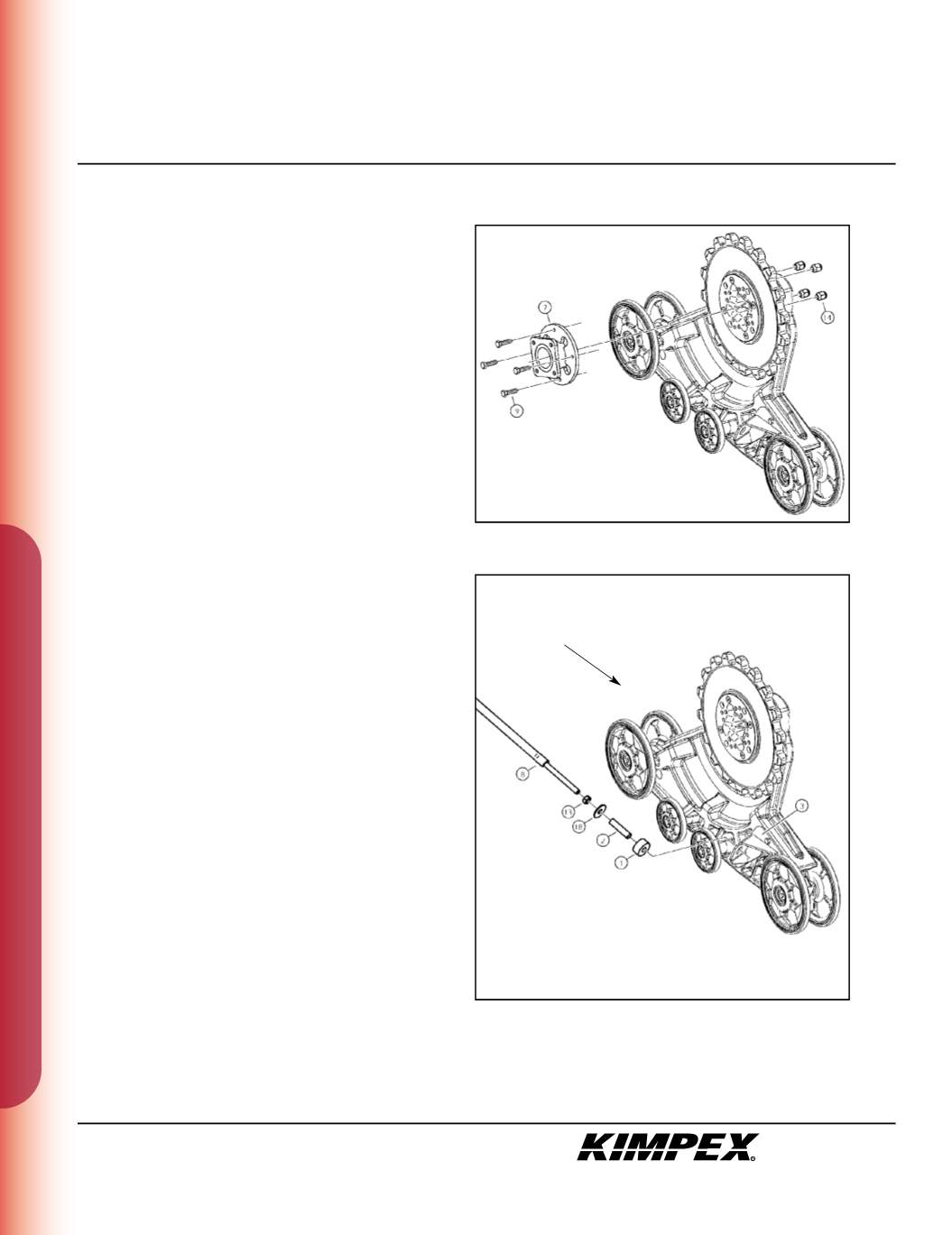
“COMMANDER WIDE TRACK” /
MAIN AXLE ADAPTER INSTALLATION
(see sketch I)
WARNING :
Prior to installation, turn off the engine, put
in two-wheel driving mode, and block the wheels.
1)
Raise the rear of the ATV off the ground and remov the wheels.
WARNING :
When the ATV is raised, make sure that it is
properly secured/supported to prevent it from
accidentally falling during the installation. If not properly
secured/supported, serious physical injury could occur.
2)
Install the
(4) M10 X 30mm
hex bolts (#
9
) into the threaded holes
of the main axle adapter (#
7
) as llustrated.
3)
Position and fasten the main axle adapter (#
7
) onto the hub of
the vehicle using the original wheel nuts. Apply the tightening
torque specified in your ATV owner’s manual.
4)
Position and fasten the Track Kit to the main axl adapter (#
7
)
using the
(4) M10
wheel nuts (#
14
).
Torque to 25 ft-lbs.
NOTE :
Recheck torque of the wheel nuts (#14) after
one hour of use.
5)
Repeat
steps 2
to
4
for the opposite side.
“COMMANDER WIDE TRACK” /
REAR ANTI-ROTATION INSTALLATION
(see sketch J)
1)
Screw the
5/8” nc
nut (#
13
) onto the threaded part of the anti-
rotation arm (#
8
).
2)
Install the
17mm I.D. X 50mm O.D. X 3mm
flat washer (#
18
) and the
bushing spacer tube (#
2
) onto the threaded part of the anti-
rotation arm (#
8
).
3)
Install the rubber bushing (#
1
) over the bushing spacer tube
(#
2
).
4)
Slide the anti-rotation arm assembly into the hole of the rear
right anti-rotation arm bracket (#
3
).
sketch I
sketch J
RIGHT
REAR VIEW
Rear of the ATV


