KIMPEX INC.
/ 5355, rue St-Roch / Drummondville (Québec) Canada / J2B 6V4
KIMPEX USA
/ 100 Walnut Street / Champlain, New York / 12919
Lithographié au Canada / Litho’d in Canada
A-2810153 Rév. A
2810153
4/6
ATV
MOUNTING INSTRUCTIONS
FRONT AND REAR A-ARM BRACKET KIT
Kimpex
# 373414
For "Commander" track kit / Polaris Sportsman
sketch B
LEFT
FRONT VIEW
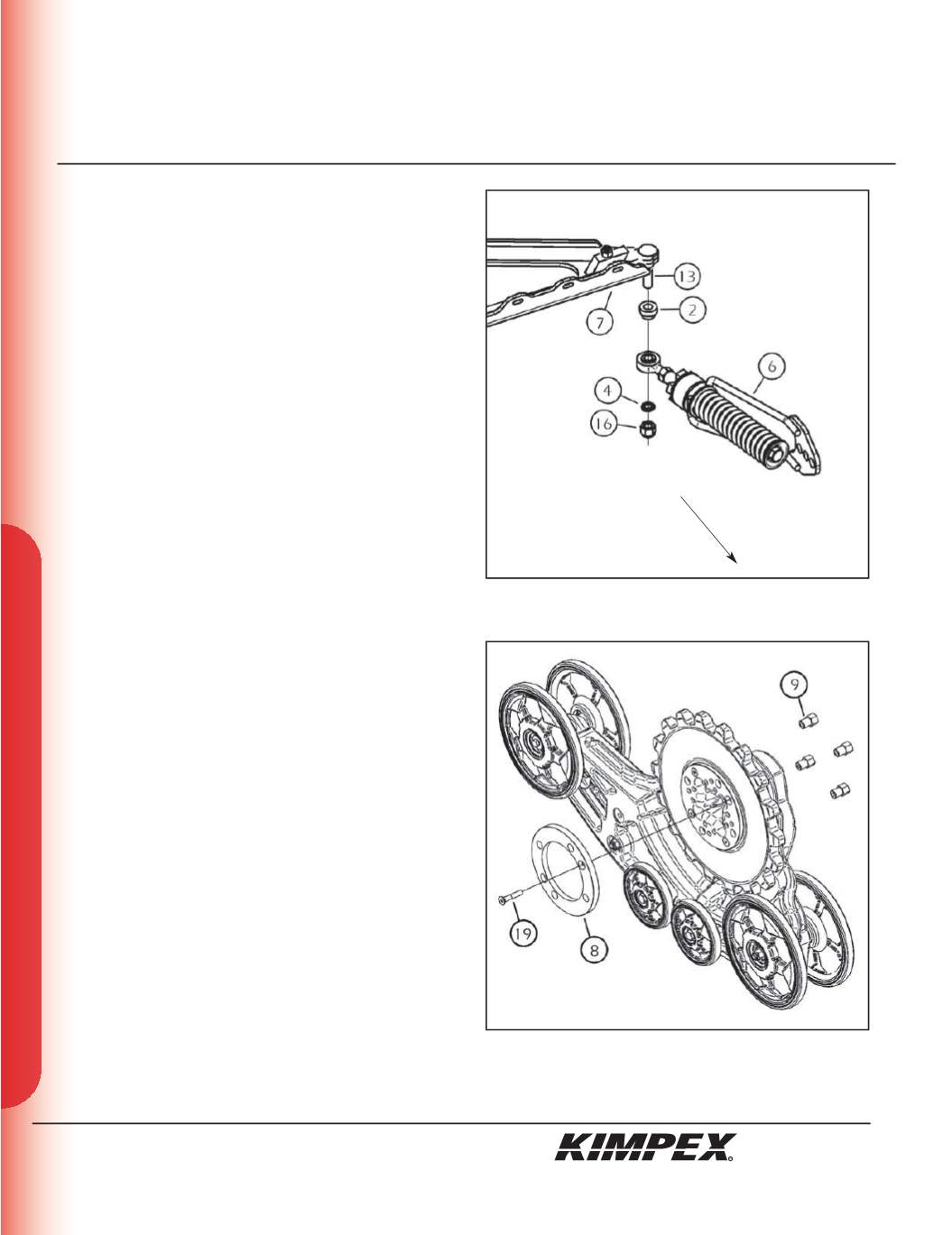
FRONT ANTI-ROTATION INSTALLATION
(see sketch B)
NOTE :
Pay special attention to the orientation given to
spacers (#2 and #4) during installation.
1)
Install the large ball joint spacer (#
2
) with the narrow part facing
down onto the
1/2” nc X 3”
carriage bolt (#
13
) installed in
step 3
at the «FRONT SUB-TABLE INSTALLATION» section
.
2)
Install the ball joint of the anti-rotation assembly (#
6
) onto the
bolt (#
13
), below the large ball joint spacer (#
2
).
Install the short ball joint spacer (#
4
) with the narrow part facing
up, below the anti-rotation assembly (#
6
).
3)
Tighten the assembly with the
1/2” nc
self-locking nut (#
16
).
Torque to 65 ft-lbs.
WARNING :
If the bolts are not sufficiently tightened,
there is a risk of them becoming loose, of parts detaching
and risk of loss of control over the vehicle, as well as risk
of personal injury.
4)
Rotate the anti-rotation assembly (#
6
) towards the center of the
ATV to prevent it from interfering with the installation of the
track kit.
5)
Repeat
steps 1
to
4
for the opposite side.
MAIN AXLE ADAPTER INSTALLATION
(see sketch C)
1)
Remove and discard only one bolt retaining the sprocket to the
main axle of the track kit.
NOTE :
Pay special attention to the orientation given to
the main axle adapter (#8) during installation. The lip, of
the main axle adapter, must fit perfectly the circumfer-
ence of the main axle.
2)
Position the main axle adapter (#
8
) and fasten using the
3/8” nc X 2-1/4”
Allen socket machine screw (#
18
).
Torque to 20 ft-lbs.
3)
Install the track kit onto the hub of the ATV using the
(4) 3/8” nc
“T” nuts (#
9
). Torque to 25 ft-lbs.
NOTE :
Recheck torque of the “T” nuts (#9) after one
hour of use.
4)
Repeat
steps 1
to
3
for the opposite side.
Front of the ATV
sketch C


